3
E. 04.99• G.13.11.07
Overview
Overview
General information / safety information
The installation of a gas-fired system must conform to extensive regulations and requirements. It is there-
fore the duty of the installer to be familiar with all applicable regulations and requirements. Installation, start-
up and maintenance must be performed with utmost care.
The burner must not be operated in rooms with high levels of air humidity (laundry rooms), dust or corrosive
vapours. The boiler room must be ventilated accordingly with ventilation air.
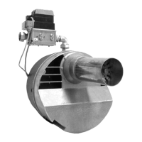
The GIERSCH RG20 / RG30 Series gas burners are suitable for burning natural gas or liquefied petroleum
gas and comply with the European standard DIN EN 676.
Caution !
Improper installation, adjustment, modification, operation or maintenance may result in physical
injury or damage to property/equipment.
Read the instructions prior to use.
This product must be installed in conformity with the valid regulations (e. g. DIN-VDE, DIN-DVGW).
The design and degree of protection of the burner make it suitable for operation in enclosed rooms.
Declaration of conformity
We declare that the Giersch RG20/30 Series gas blower burners with the assigned
product identification numbers:
RG20 CE-0085 AP 0364
RG30 CE-0085 AP 0365
satisfy the basic requirements of the following directives:
• “Low Voltage Directive” according to 73/23/EEC in conjunction with DIN VDE 0700 Part 1 / Ed. 04.88
and DIN VDE 0722 / Ed. 04.83
• “Electromagnetic Compatibility” according to Directive 89/336/EEC in conjunction with EN 55014 / Ed.
04.93 and EN 50082-1 / Ed. 01.92
• “Gas Burning Installations Directive” according to Directive 90/396/EEC in conjunction with DIN EN
676 / Ed. 12.96 and DIN EN 437 / Ed. 03.94
• “Efficiency Directive” according to Directive 92/42/EEC in conjunction with DIN EN 676/ Ed. 12.96
• “Machinery Directive” as per directive 98/37/EEC
These products conform to the design checked at the Department 0085 mentioned.
Checking scope of delivery and connection data
Before installing the GIERSCH gas burner, please check that all items included in the scope of delivery are
present.
Scope of delivery:
Burner, sliding flange and gasket, 4 retaining screws, separate operating instructions, technical informati-
on, one 7-pin and one 4-pin connector (for -Z and -M only).
Compact gas unit and gaskets (for KEV only: additionally blue hoses for furnace and air pressure connec-
tions, see Overview, Page 10).
The gas pipe must be designed to conform to the flow rate and the available gas flow pressure and routed
with the lowest pressure loss over the shortest distance to the burner. The loss of gas pressure via the com-
pact unit and the burner and the resistance on the fuel gas side of the heat generator must be less than
the connection flow pressure.
Caution !
Observe throughflow direction of compact unit.