5
E. 04.99• G.13.11.07
Installation
Installation
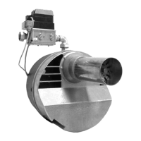
Installing flange and burner
When installing the sliding flange, only tighten screws
1 and 2 otherwise it will not be possible to secure the
burner pipe with screw 3. Slide in the burner, adjust to
furnace depth and tighten the screws in the following
sequence: 3, 4, 5, raising the housing in the process.
Important: Secure the sliding flange so that the clam-
ping screw 3 is positioned at the top.
Checking electrode setting
• Move the burner into the service position as
described on Page 25.
• Check the setting of the ignition and ionisation elec-
trodes (see Page 25).
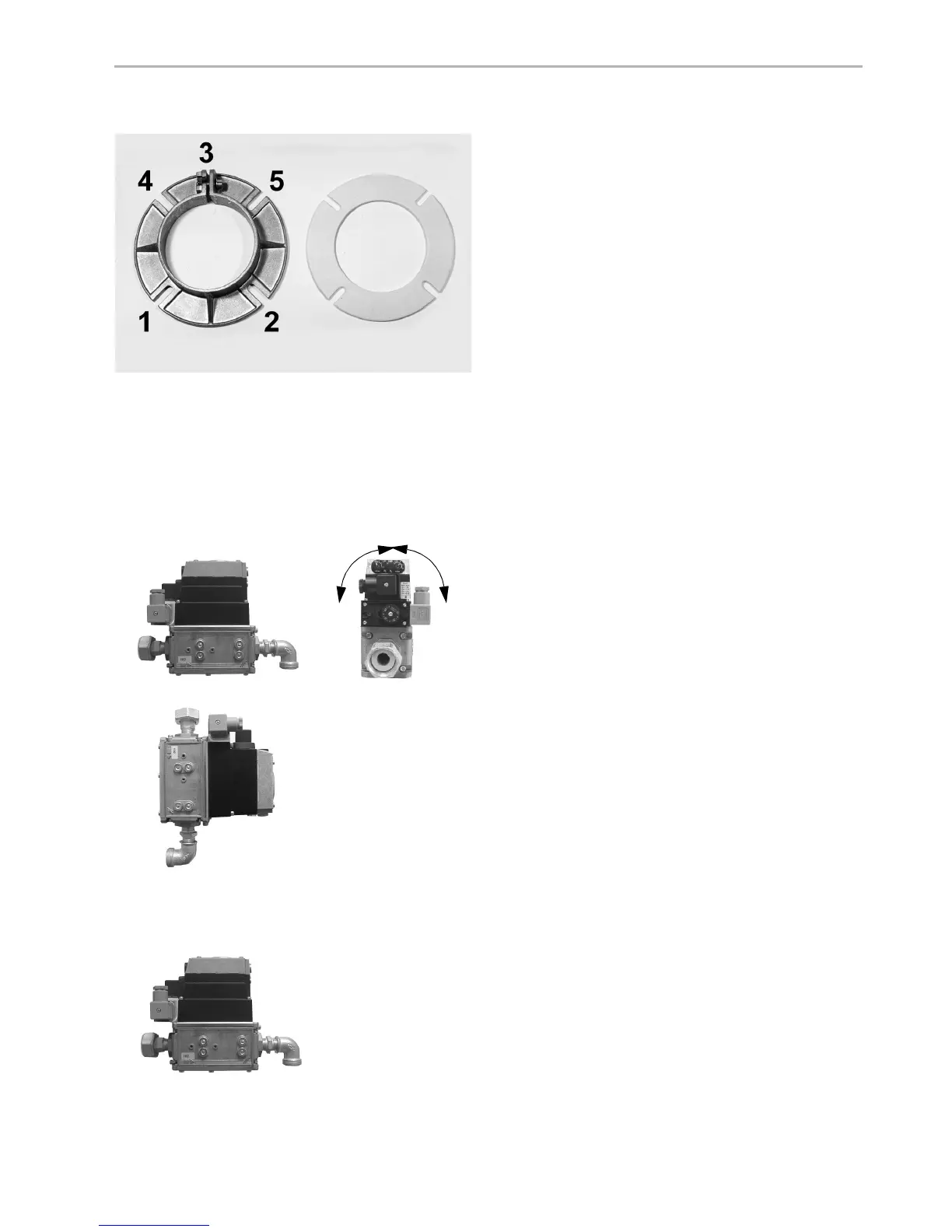
Installing gas assembly
• Remove plastic protective plug.
• Install unions including accompanying seals.
• Observe installation position.
• Check connecting point of gas assembly with
noncorrosive foaming agent for leaks and vent gas
pipe.
• When venting gas, discharge safely to atmosphere
with a hose.
Comply with DVGW-TRGI 1986/96 Section 7, TRF
1988, DIN 4756 and local regulations.
If proportional pressure control RG20/30(-Z-)-M-L with
KEV:
Fit the furnace pressure meter tube to the boiler door
with the gradient towards the boiler (if required).
Lay the control lines to the KEV to the corresponding
ports P
L
and P
F
. Use the blue PU hoses supplied.
• Lay the control line so that no condensate can flow
into the KE.
• Connect hose to furnace pressure meter tube with
port P
F
(if required).
• Connect hose to port P
L
with measuring nipple for
air pressure on burner base plate.
If this connection is not made, the magnetic valves
will not open.