- 20 -
Before installing the devices, be sure to turn off the devices and your computer. Unplug the power
cord from the power outlet to prevent damage to the devices.
For how to turn on/off the lights of the LED strip, please navigate to the "Unique Features" page
of GIGABYTE's website.
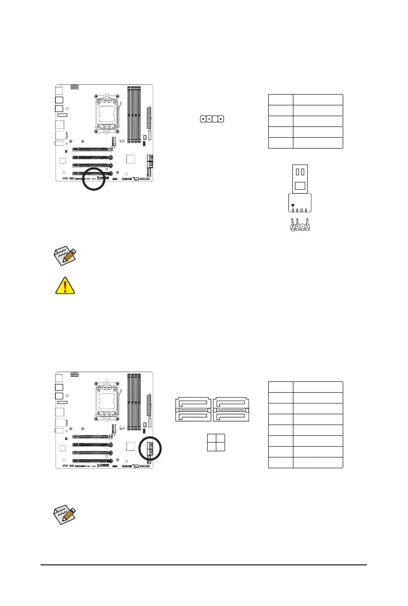
6) D_LED (Addressable LED Strip Header)
The header can be used to connect a standard 5050 addressable LED strip, with maximum power rating
of 5A (5V) and maximum number of 1000 LEDs.
Pin No. Denition
1 V (5V)
2 Data
3 No Pin
4 GND
Connect your addressable LED strip to the header. The power pin
(marked with a triangle on the plug) of the LED strip must be connected
to Pin 1 of the addressable LED strip header. Incorrect connection may
lead to the damage of the LED strip.
Addressable LED
Strip
1
1
F_USB30
F_U
B_
F_ F_
_
B
BS_
B
SB_
B
_S
S_
_
B
_U
_
B
S
123
123
123
123
1
1
1
1
BSS
S
_S
SSU
1 2 3
S3
BSSS
U
__ 3
F_USB3F
S _
S _
S _
SF
B_
B_
F
_0
S
S
_0F
_F
_
_
__B
U
S _S
_
SF_
B
USB0_B
B_
B_
F_USB3
F_USB303
_
_3U
S_
_S
SS_F
_
_
F
_SB
F_
Pin No. Denition
1 GND
2 TXP
3 TXN
4 GND
5 RXN
6 RXP
7 GND
SATA3
2 0
3 1
To enable hot-plugging for the SATA ports, please navigate to the "BIOS Setup" page of GIGABYTE's
website and search for "SATA Conguration" for more information.
1
1
7
7
7) SATA3 0/1/2/3 (SATA 6Gb/s Connectors)
The SATA connectors conform to SATA 6Gb/s standard and are compatible with SATA 3Gb/s and SATA
1.5Gb/s standard. Each SATA connector supports a single SATA device. The SATA connectors support
RAID 0, RAID 1, and RAID 10. Please navigate to the "Conguring a RAID Set" page of GIGABYTE's
website for instructions on conguring a RAID array.