- 14 -
8S651MP-RZ Series Motherboard
English
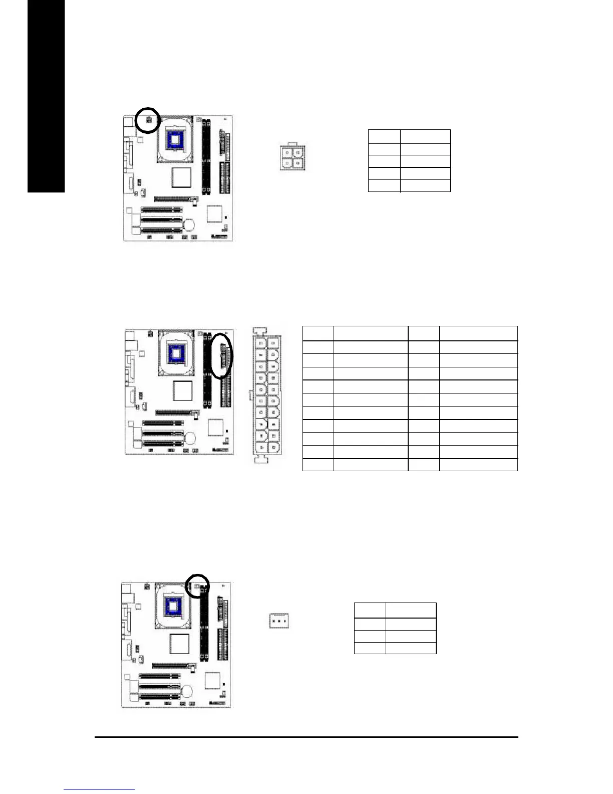
1) ATX_12V (+12V Power Connector)
This connector (ATX _12V) suppliesthe CPU operation voltage (Vcore).
If this " ATX_ 12V connector" is not connected, system cannot boot.
Pin No. Definition
1 GND
2 GND
3 +12V
4 +12V
2) ATX (ATX Power)
AC power cord should only be connected to your power supply unit after ATX power cable and other
related devices are firmly connected to the mainboard.
1
1 0
2 0
1 1
Pin No. Definition
1 3.3V
2 3.3V
3 GND
4 VCC
5 GND
6 VCC
7 GND
8 Power Good
9 5V SB (stand by +5V)
10 +12V
Pin No. Definition
11 3.3V
12 -12V
13 GND
14 PS_ON(soft on/off)
15 GND
16 GND
17 GND
18 -5V
19 VCC
20 VCC
3
1
4
2
3) CPU_FAN (CPU FAN Connector)
Please note, a proper installation of the CPU cooler is essential to prevent the CPU from running
under abnormal condition or damaged by overheating.The CPU fan connector supports Max.
current up to 600 mA.
Pin No. Definition
1 GND
2 +12V
3 Sense
1
 Loading...