- 26 -
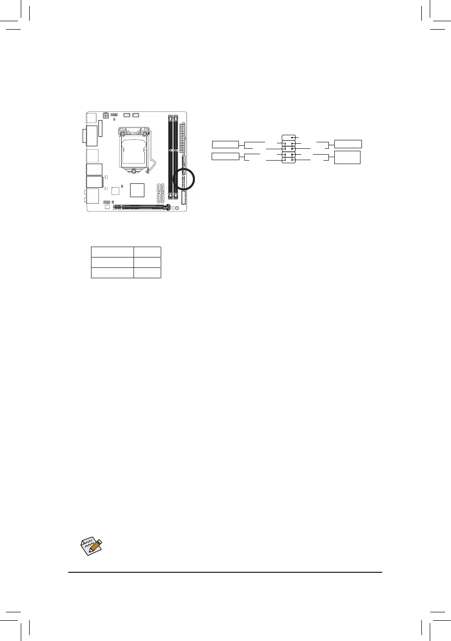
8) F_PANEL (Front Panel Header)
Connect the power switch, reset switch, and system status indicator on the chassis to this header according
to the pin assignments below. Note the positive and negative pins before connecting the cables.
The front panel design may differ by chassis. A front panel module mainly consists of power switch,
reset switch, hard drive activity LED and etc. When connecting your chassis front panel module
to this header, make sure the wire assignments and the pin assignments are matched correctly.
• PW(PowerSwitch,Red):
Connectstothepowerswitchonthechassisfrontpanel.Youmaycongurethewaytoturnoffyour
systemusing the powerswitch (refer to Chapter2, "BIOS Setup,""Power Management," formore
information).
• HD (HardDriveActivityLED,Blue):
Connects to the hard drive activity LED on the chassis front panel. The LED is on when the hard drive
is reading or writing data.
• RES (ResetSwitch,Green):
Connects to the reset switch on the chassis front panel. Press the reset switch to restart the computer
ifthecomputerfreezesandfailstoperformanormalrestart.
• NC(Purple):
No connection.
• PLED (PowerLED,Yellow):
Connects to the power status indicator on the chassis front panel. The LED
is on when the system is operating. The LED is off when the system is in S3/
S4sleepstateorpoweredoff(S5).
System Status LED
S0 On
S3/S4/S5 Off
1
2
9
10
NC
PLED-
PW-
PLED+
PW+
HD-
RES+
HD+
RES-
Power Switch
Hard Drive
Activity LED
Reset Switch
Power LED
 Loading...