- 20 -
Hardware Installation
21
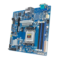
3) SATA_0_1/SATA_2_3 (SATA III 6Gb/s Connectors)
The SATA connectors conform to SATA III 6Gb/s standard and are compatible with SATA 3Gb/s standard.
Each SATA connector supports a single SATA device.
PinNo. Denition
1 GND
2 TXP
3 TXN
4 GND
5 RXN
6 RXP
7 GND
1
7
21
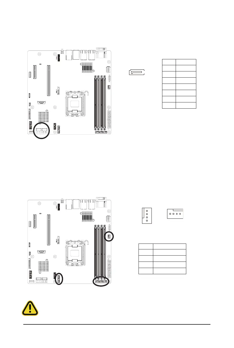
4/5/6) CPU0_FAN/SYS_FAN1/SYS_FAN2/SYS_FAN3/SYS_FAN4/SYS_FAN5 (Fan Headers)
Themotherboardhasone4-pinCPUfanheader(CPU_FAN),andve4-pin(SYS_FAN)systemfanheaders.
Most fan headers possess a foolproof insertion design. When connecting a fan cable, be sure to connect
it in the correct orientation (the black connector wire is the ground wire). The motherboard supports CPU
fan speed control, which requires the use of a CPU fan with fan speed control design. For optimum heat
dissipation, it is recommended that a system fan be installed inside the chassis.
1
1
PinNo. Denition
1 GND
2 +12V
3 Sense
4 Speed Control
•
Be sure to connect fan cables to the fan headers to prevent your CPU and system from
overheating. Overheating may result in damage to the CPU or the system may hang.
•
Thesefanheadersarenotconfigurationjumperblocks.Donotplace ajumpercaponthe
headers.
 Loading...