GD-Link Adapter User Guide
6
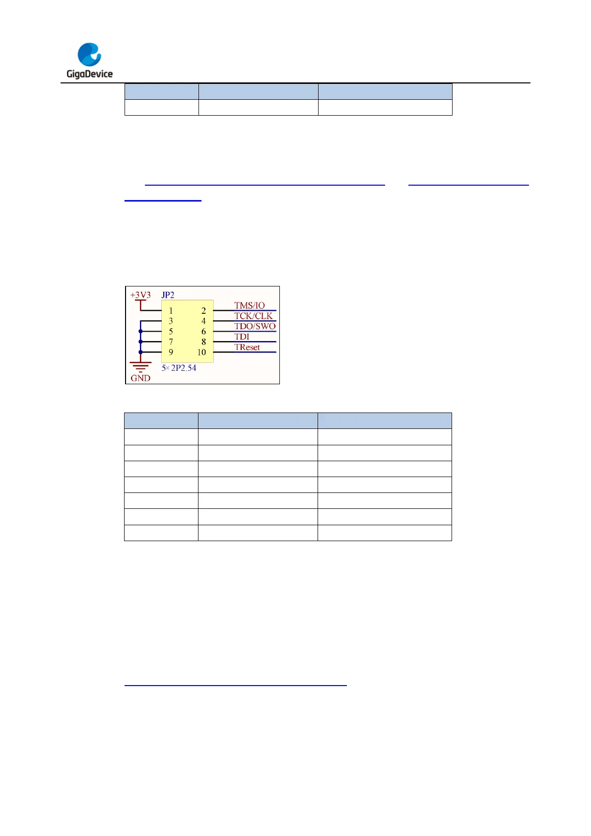
2.2. Connecting GD-Link adapter with target board
The Figure 2-2. Schematic diagram of GD-Link adapter and Table 2-2. Pin function of
GD-Link adapter shows the electrical connection relationship between GD-Link adapter and
SWD interface of the target board, according to the information, connect GD-Link adapter
with target board via DuPont lines or other connecting wires.
Note: It is recommended that the length of the DuPont lines not exceed 10cm.
Figure 2-2. Schematic diagram of GD-Link adapter
Table 2-2. Pin function of GD-Link adapter
3. Offline programming
3.1. Tool download
When using the GD-Link offline programming function, please download the latest version of
the PC tool GigaDevice GD-Link Programmer from the website
https://www.gd32mcu.com/cn/download/7?kw= and perform the following operations.
3.2. Update user code
Plug GD-Link adapter into PC USB connector, LED4 will turn on, which indicates that GD-