Do you have a question about the GILES Chester Fried CF 400 and is the answer not in the manual?
Important warnings and precautions for user safety during operation and maintenance.
Information on how to obtain repair or assistance and required details.
Step-by-step procedures for proper fryer installation and safety precautions.
Guidance on safely removing the fryer from its shipping crate.
Requirements and considerations for proper fryer ventilation.
Essential electrical grounding, voltage, and phase specifications for installation.
Key safety precautions and guidelines for operating the fryer.
Detailed descriptions of the control panel buttons, lights, and their functions.
Identification and function of parts located in the fryer's lower cabinet.
Descriptions of components within the main cooking vessel, including probes and heating elements.
Explanation of charcoal, EAC, and baffle filters for ventless hood systems.
Overview of special cooking computer functions like melt and cool-down cycles.
Explanation of the operation and purpose of the cooking computer's keypad.
Step-by-step instructions for programming menu times and temperatures.
Initial control settings required before performing fryer tests.
Procedure to verify the proper functioning of the fryer's heating elements.
Steps to test the functionality of the oil filter pump.
Detailed instructions for the initial cleaning and preparation of the fryer.
Procedures for cleaning the filter pan and replacing the filter paper.
Specific cleaning guidance for components of the ventless hood system.
Steps for removing and replacing charcoal and EAC filters in the hood system.
How to use the fryer controls to initiate and manage the cooking process.
The recommended procedure for filtering the fryer's oil to maintain quality.
Monthly inspection and testing procedures for the safety interlock system on VH models.
Overview of the Ansul R-102 fire suppression system installed in the fryer.
Details on factory and distributor installed components of the fire suppression system.
Information regarding the requirements and placement of the remote manual pull station.
Guidelines for routine maintenance of the fire suppression system.
Procedures for semi-annual, annual, and 12-year service by qualified personnel.
The procedure for marinating chicken to enhance flavor, moisture, and tenderness.
Steps for batter dipping chicken to ensure flavor and breading adhesion.
The final step of coating chicken with breading mix before frying.
Guidelines for loading chicken pieces into the fryer basket for optimal cooking.
Advice on using IQF and pre-marinated chicken products as alternatives.
Instructions on when and how to stir chicken during the cooking cycle.
Procedure for preparing potato wedges for frying, including marination.
Solutions for common problems related to the fryer's temperature control and cooking computer.
Troubleshooting steps for issues with the basket lift and oil filtration mechanisms.
A list of parts associated with the front control panel of VH fryer models.
A list of parts found in the rear view of the fryer's lower cabinet.
A list of parts located in the rear view of the fryer's header section.
A list of parts for the upper hood section of VH models.
A list of parts comprising the fryer's filter pan assembly.
Part list specific to the 1-phase wiring of CF-400/500 models.
Part list specific to the 3-phase wiring of CF-400/500 models.
Part list specific to the 1-phase wiring of CF-400 VH models.
Part list specific to the 3-phase wiring of CF-400 VH models.
Part list specific to the 1-phase wiring of CF-500 VH models.
Part list specific to the 3-phase wiring of CF-500 VH models.
Schematic diagram illustrating the electrical connections for CF-400/500 models.
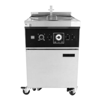
| Model Number | CF 400 |
|---|---|
| Capacity | 4.0 lbs |
| Material | Stainless Steel |
| Phase | 1 |
| Dimensions | 18" x 18" x 18" |