11
Lubricate the following parts on a regular basis, but not as
often as the wrist pin assemblies:
Upper Connecting Rod Bearings
Access: Holes in front of top cover�
Lower threaded blocks (TS-2 Only)
Access: Panels on sides of machine case�
Removal of Top and Side/Back Covers
Disconnect power supply before
servicing or cleaning.
DO NOT plug in or operate the
Testing Screen without all covers installed.
TS-1/TS-3: Unscrew the knob on the pump handle�
Remove the thirteen screws that secure the top cover,
then remove the cover� Reinstall the knob�
TS-2: Turn the clamp rod handles so they point sideways
and away from the machine� Remove the thirteen screws
that secure the top cover, then remove the cover�
TS-1, TS-2, TS-3: Loosen or remove the ve screws that
secure the side/back cover� Pivot the cover toward the back
of the machine, allowing it to be supported by the motor
wire�
Drive Assembly
Disconnect power supply before
servicing or cleaning.
DO NOT plug in or operate the
Testing Screen without all covers installed.
V-belt
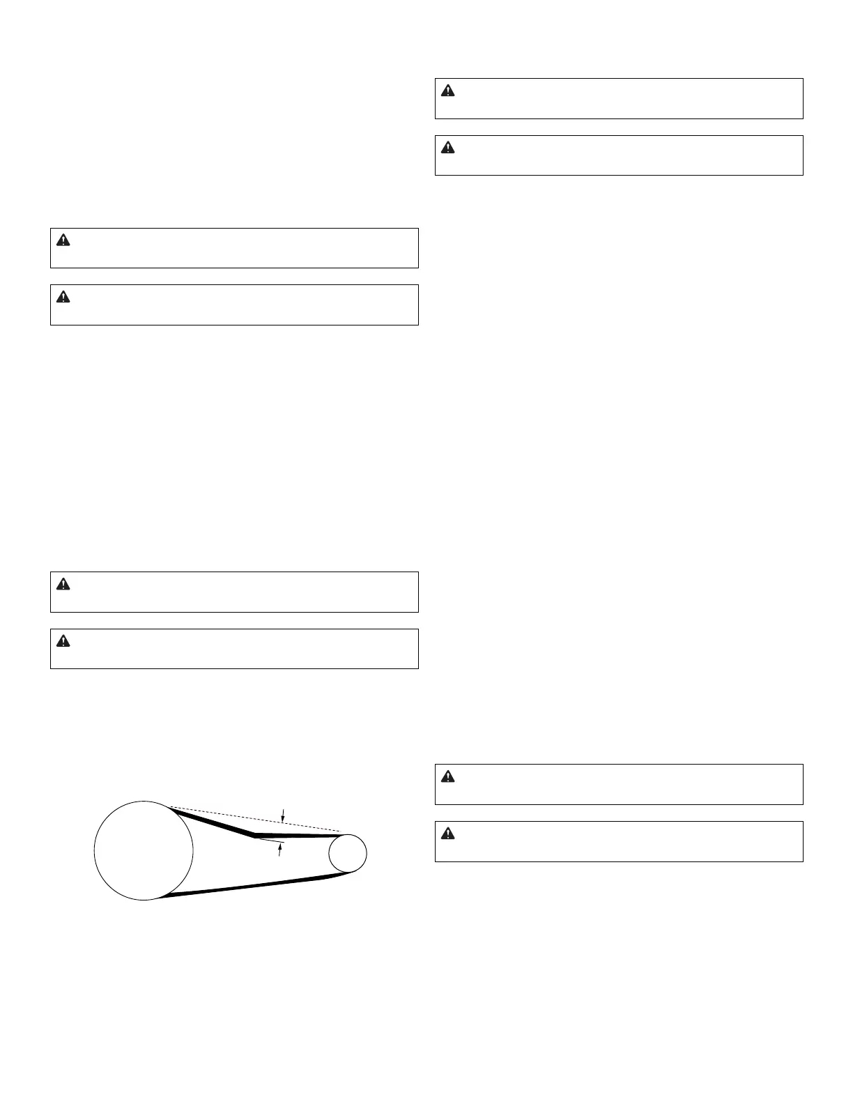
Periodically check the motor V-belt for wear, tension, and
alignment� The belt should be snug, neither too tight nor
too loose. It should deect about 1/4in (6mm) at the center
point between the pulleys (Fig� 5)�
1/4” (6mm)
Fig. 5: Correct V-belt tension
A worn, loose, tight, or misaligned V-belt can adversely af-
fect the operation of the Testing Screen. A good t assures
longer life, less bearing wear, and quieter operation than a
belt which is too tight� A loose belt may cause the machine
to run too slowly or to slip�
Adjust or Replace the V-belt
Disconnect power supply before
servicing or cleaning.
DO NOT plug in or operate the
Testing Screen without all covers installed.
1. Remove the top and side/back covers�
2. Loosen the motor mounting bolts�
3. Verify that the pulleys are aligned and adjust if
necessary� Move the motor until the correct belt tension
is obtained (Fig� 5)�
4. Tighten the motor mounting bolts then re-verify the
belt tension�
V-belt Replacement
1. Loosen the motor mounting bolts and move the motor
toward the front of the machine until the belt disengages
from the motor pulley�
2. Insert a pry bar under the front of the case top and
over the top of the Vibrating Unit Assembly� Shift the
Vibrating Unit Assembly until the holes in the Vibrating
Unit Assembly and in connecting rod align� Remove the
shoulder bolt�
3. Rotate connecting rod upward until you can remove
the belt�
4. Install the new V-belt around the connecting rod�
5. Replace the shoulder bolt then place the V-belt around
the pulleys� Make sure that the pulleys are aligned�
6. Move the motor toward the rear of machine until the
correct belt tension is obtained (Fig� 5)� Tighten the
motor mounting bolts then re-verify the belt tension�
Connecting Rod Assembly
Disconnect power supply before
servicing or cleaning.
DO NOT plug in or operate the
Testing Screen without all covers installed.
Gilson recommends replacing the connecting rods as com-
plete assemblies to avoid t and tolerance problems during
installation� Use the following procedure: