8
3. Apply clamping force to hold the screen tray that extends
from the front of the Testing Screen�
TS-1/TS-3: Apply short strokes to the hydraulic
pump handle�
TS-2: Turn the two clamp rods simultaneously and as
equally as possible, using your sense of touch to determine
when the trays are rmly clamped.
4. Place a level on the protruding screen tray then re-level
the Testing Screen by adding or removing shims until
the Vibrating Unit Assembly and screen tray are level
side-to-side and front-to-back. Give mounting nuts a nal
tightening�
5. Release clamping pressure and put desired screen trays
into the machine�
Hydraulic System Check
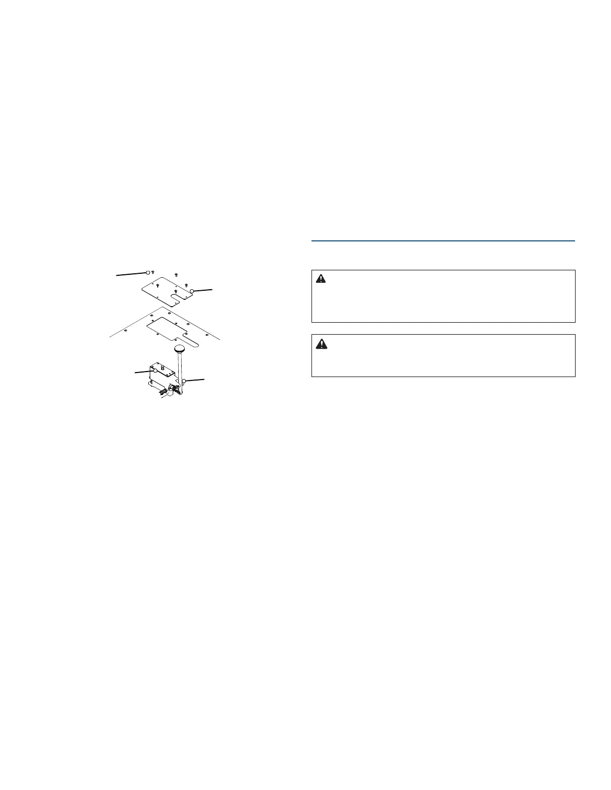
Screws (5x)
External
Pump
Cover
Pump
Cover
Hydraulic
Pump
Fig. 3: TS-1/TS-3 Hydraulic Pump Access
If you have a TS-1 or TS-3 Hydraulic Testing Screen,
examine and test the hydraulic system for leaks�
1. Remove the ve screws that secure the external pump
cover to the top, then lift the cover o (Fig. 3).
2. Observe the position of the internal pump cover before
you remove it� Its vent is slightly closer to the front
(handle) end of the pump than to the back� Gilson
recommends using a marker or other means to mark the
operator side of the cover to ensure correct orientation
during reassembly�
3. Check the oil level in the pump� It should be 1/4in from
the top of the reservoir� If not, refer to instructions for
replacing hydraulic oil on page 14� Reinstall the external
pump cover�
Verify Power Requirements
Verify that the Testing Screen is wired as ordered and
appropriate for your power source�
Standard Testing Screens are driven by a 115V/60Hz,
1/2hp electric motor requiring 12-15 amps to operate.
A dedicated 20 amp circuit is recommended. Machines
with model numbers ending in “F” are congured to
operate on 230V/50Hz.
• Locate the voltage label on the back of the Testing
Screen, and check to be sure that the machine is wired
as ordered�
• Make sure your electrical power source is of a like
conguration.
• Make sure the Testing Screen and your electrical power
source are properly grounded�
• Make sure the power switch (located on right, vertical
surface of the top cover) is in the OFF position�
Testing Screen Power OFF:
• GREEN button OUT
• RED button IN
Operation
TS-1/TS-2/TS-3 Operation
Read and understand ALL of the
safety and operating instructions and sample capac-
ity information in this manual before operating the
Testing Screen.
DO NOT wear loose clothing which
can get caught on the clamp rods while making this
adjustment.
NOTE: These instructions cover operation of the Testing
Screen, not performance of any test�
1. Locate the Testing Screen’s power switch on the right,
vertical surface of the top cover�
Make sure that the switch is in the OFF position:
• GREEN button OUT
• RED button IN
Plug the three-pronged plug into a properly-grounded
power source; or otherwise properly ground your Testing
Screen�
2. Release the clamping force of the Vibrating Unit
Assembly:
TS-1/TS-3: Pull the hydraulic pump handle all the way
toward the front of the machine�
TS-2: Turn clamp rods counterclockwise�
3. Load the Testing Screen:
Load your desired sequence of screen trays into your
Testing Screen, being careful not to pinch your ngers with
already inserted screen trays� Apply clamping force on the
trays�
TS-1/TS-3: Apply short strokes to the hydraulic pump han-
dle� The hydraulic system will apply tension on both sides
of the Vibrating Unit Assembly�