7
Lag screw mounting
Mounting hardware is not provided� These additional items
are required for proper lag screw installation on a poured
concrete oor:
Hardware Quantity
0�5in lag screws 4
0�5in lag shield anchor 4
Metal shims Varies
Procedure
1. Place the unit in the desired location. Mark the oor in
the center of the mounting feet�
2. Using lifting equipment, move the unit�
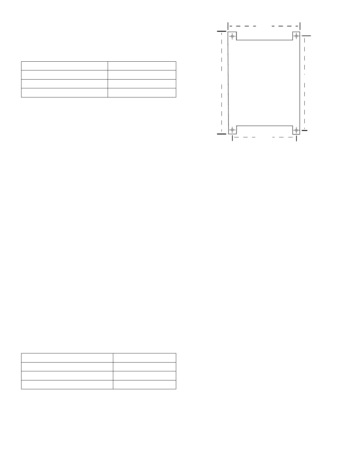
3. Conrm marked mounting location matches the
mounting template (Fig� 2)�
4. Install the lag screw shield anchors in the marked
locations�
5. Using lifting equipment, return the unit to the mounting
location�
6. Place a at washer on the lag bolts and install the lag
screws in the mounting anchors� Do not fully tighten the
screws�
7. Initially level the units’ outer case, both front-to-back and
side-to-side� Do this by placing and/or removing metal
shims under the feet until the top of the unit is level along
all four edges�
NOTE: The Testing Screen must be level for proper test
results and best operation of the machine�
8. Tighten the lag bolts equally on all four mounting feet,
making sure the unit’s case remains level�
Anchor bolt mounting
Mounting hardware is not provided� These additional items
are required for proper anchor bolt installation on a poured
concrete oor:
Hardware Quantity
0�5in anchor bolts 4
0�5in lock nuts 4
Metal shims Varies
Procedure
1. Place the unit in the desired location. Mark the oor in
the center of the mounting feet�
2. Using lifting equipment, move the unit�
3. Conrm marked mounting location matches the
mounting template (Fig� 2)�
4. Install the anchor bolts in the marked locations, leaving
1�5in of thread exposed to allow for the mounting feet,
shims, and nuts�
5. Using lifting equipment, place the unit on the anchor
bolts, so that the threads extend through the holes in the
mounting feet�
6. Place mounting nuts on the anchor bolts to protect the
threads while leveling� Use lock nuts or other appropriate
locking fastener�
7. Initially level the units’ outer case, both front-to-back and
side-to-side� Do this by placing and/or removing metal
shims under the feet until the top of the unit is level along
all four edges�
NOTE: Note: The Testing Screen must be level for proper
test results and best operation of the machine�
8. Tighten the mounting nuts equally on all four mounting
feet, making sure the unit’s case remains level�
Level the Vibrating Unit Assembly
1. Release the clamping force:
TS-1/TS-3: Pull the handle on the hydraulic pump all the
way toward the front of the machine to release hydraulic
clamping force� Remove the screen trays
if present�
TS-2: Turn the manual screw-type clamp rods counter-
clockwise to release clamping force� Remove the screen
trays if present�
2. Insert a screen tray into the third screen tray position
from the top of Vibrating Unit Assembly, leaving 1/3 of its
length extended out of the front of the machine�
34” 32”
20.50”
Fig. 2: Mounting Template