Transport and location 33
Cod.nº 429043
Rev. No. 21/0519
2.6.2. HS-6023, EH055 models
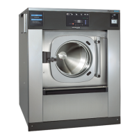
• Remove the screws (Fig. 2.6/A) holding the lower front cover and loosen the three screws (Fig. 2.6/B)
holding the base of the chassis.
• Separate the rubber profile (Fig. 2.6/C) at the two small side guards and remove the front cover
(Fig. 2.6).
• Remove the screws holding the rear cover and remove it.
• Locate on the chassis base the two yellow fixing profiles and dismantle them. The profiles are secured
with screws (Fig. 2.7).
• Assemble the rear cover.
• Assemble the front cover and place the rubber profile at the small side guards.
CAUTION!
The rubber profile is a protection against cutting and catching. Check that it is properly fixed on the
front cover and side covers.
Fig. 2.6 Fig. 2.7
•
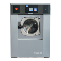
Assemble the toe plate (Fig. 2.8). This
piece is shipped disassembled from the
machine.
•
Fit the perforated metal plate onto the
lower aperture at the back of the machine.
•
Both protections are dispatched
dismantled from the rest of the machine,
and the securing screws are screwed into
the respective securing points.