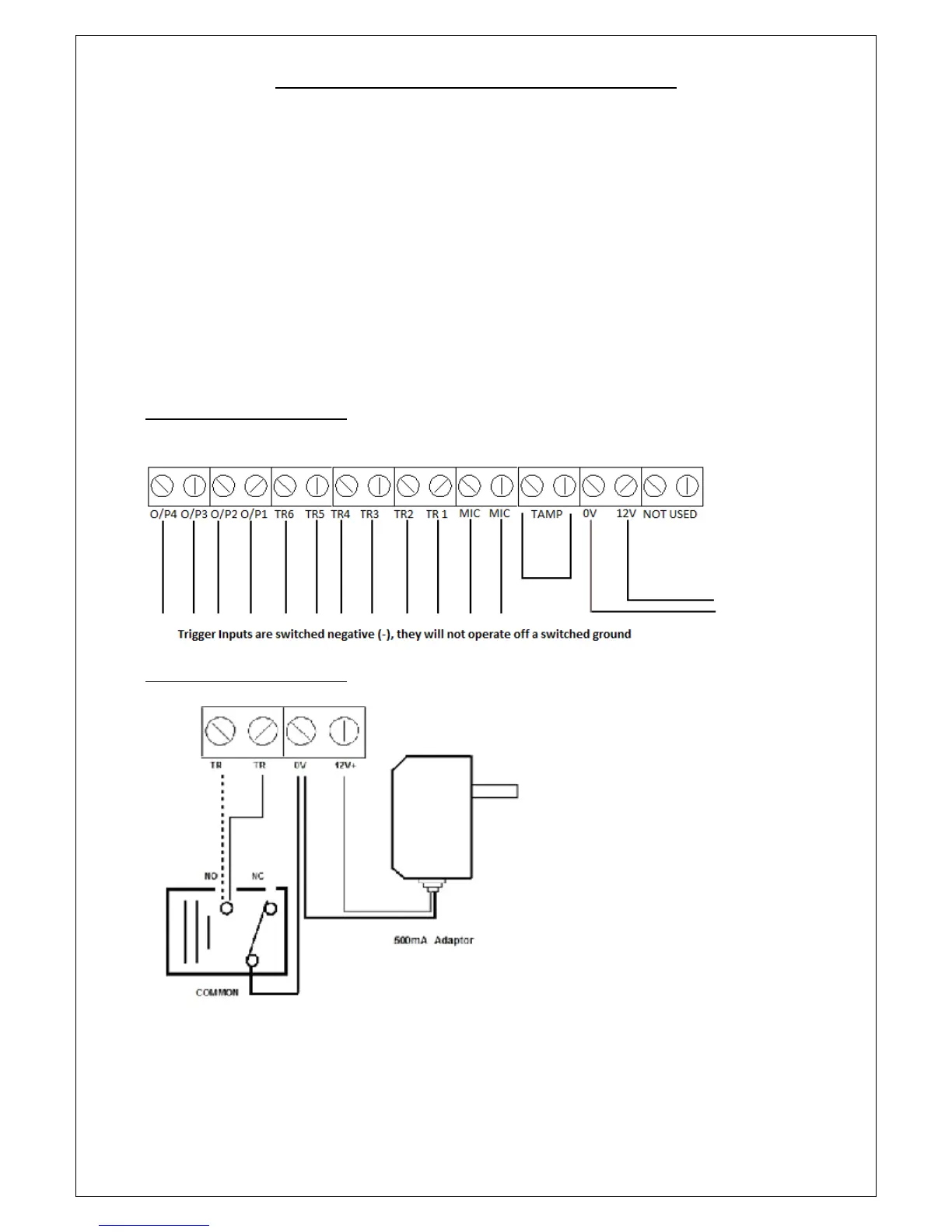
CONNECTIONS ON THE COMMUNICATOR
The Trigger terminals are for connection to a switched negative output of an Alarm System’s Bell or Siren (Fig 1
below). If such switched negative triggers are not available, connect the trigger inputs to a N.O. (normally
open) relay output with the relay common to OV (Fig 2).
The output terminals are all switched negative (max 100mA). Connect the connected device’s positive pin to
the 12V terminal and the device’s negative pin to the respective output terminal (O/P1, O/P2, O/P3 or O/P4).
The Power terminals are connected to a 12V power supply, either directly to an Alarm Control Panel’s 12V
supply or via a regulated 12V 500mA mains power adaptor.
The MIC terminals are for connection to an optional external microphone for improved “listen-in”.
IMPORTANT: The Tamper terminals are for connection to the N.C. (Normally Closed) tamper inputs on an
Alarm Control Panel. If they are not being used, please fit a loop of cable as shown.
FIG 1 – TERMINAL CONNECTIONS
FIG 2 – TERMINAL CONNECTIONS
Page 3