EB-3531
Specifications are subject to be changed without notice.
Page 9 of 21
Version 1.2.1
Layout Rules
Do not route the other signal or power trace under the engine board.
* RF:
This pin receives signal of GPS analog via external active antenna. It has to be a controlled
impedance trace at 50ohm.
Do not place the RF traces close to the other signal path and not routing it on the top layer.
Keep the RF traces as short as possible.
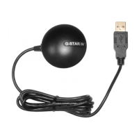
* Antenna:
Keep the active antenna on the top of your system and confirm the antenna radiation
pattern、axial ratio、power gain、noise figure、VSWR are correct when you Setup the antenna
in your case.
GPS Passive (or Active) Antenna Specifications (Recommendation)
Frequency: 1575.42±2 MHz
Axial Ratio: 3 dB Typical
Output Impedance: 50
Polarization: RHCP
Output VSWR: 1.5 Max.
Active option
Low Noise Amplifier:
Amplifier Gain: 18~22dB Typical
Output VSWR: 2.0 Max.
Noise Figure: 2.0 dB Max.
Antenna Input Voltage: 2.85V Typical