0020140413_01 - 09/12 - Glow-worm
9 Evacuation of combustion gas
9.1 Regulation
b
ATTENTION:
Only ue accessories supplied by Glow-worm must be
used.
Dierent ue outlet congurations can be carried out.
• Consult your supplier for more information about the other
possibilities and associated accessories.
44 mm/m
1 2
34
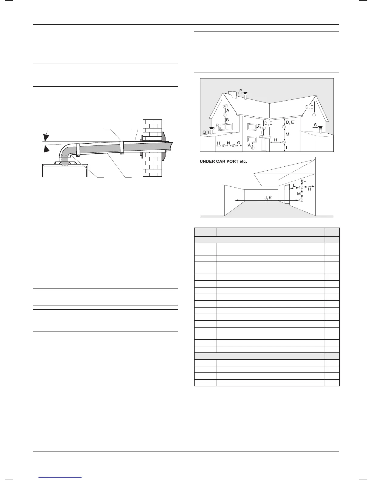
• Standard ue terminal kits have an in-built fall back to the
boiler to drain the condensate. These can be tted level
between the appliance and the termination position. All other
extended ues must have a fall of at least 44mm/m
The maximum length of the ue outlet is dened according to its
type (for example C13).
• Whatever the kind of ue system chosen, observe the
minimum distances indicated in the chart below to position
the ue terminals.
• To install the ue, refer to the separate ue instruction
supplied with your appliance.
• Explain these requirements to the user of the appliance.
a
DANGER:
If necessary, you must install a ue terminal guard.
b
ATTENTION:
Caution! The connection between the ue elbow and the
ue outlet must be sealed.
In GB the minimum acceptable siting dimensions for the terminal
from obstructions, other terminals and ventilation openings are
shown in diagram overleaf.
In IE the minimum distances for ue terminal positioning must be
those detailed in I.S.813 “Domestic Gas Installations”.
The terminal must be exposed to the external air, allowing free
passage of air across it at all times.
Being a condensing boiler some pluming may occur from the ue
outlet. This should be taken into consideration when selecting
the position for the terminal.
Carports or similar extensions of a roof only, or a roof and one
wall, require special consideration with respect to any openings,
doors, vents or windows under the roof. Care is required to
protect the roof if made of plastic sheeting. A carport is dened
as a roof and one wall.
b
ATTENTION:
If the ue terminal is positioned near a light source
insects may enter the ue system. Where safe and
practical to do so advise the homeowner to check the
ue outlet and clear visible insects from the terminal
end.
Position Positionoftheueterminal mm
Horizontalues
A
directly below an opening, air brick,
opening windows
300
B above an opening, air brick, opening windows 300
C
horizontally to an opening, air brick, opening
windows
300
D below gutter, drain/soil pipe 25
E below eaves 25
F below a balcony or car port 25
G from vertical drain pipes and soil pipes 25
H from internal/external corners 25
H* to a boundary alongside the terminal 300
I above adjacent ground or balcony level 300
J* from surface or a boundary facing the terminal 600
L
from opening (door/window) in car port
into dwelling
1200
M vertical from a terminal 1500
N horizontally from a terminal 300
Verticalues
P from another terminal 600
Q above roof level 300
R from adjacent opening window 1000
S from adjacent wall to ue 300
(*) These dimensions comply with the building regulations,
but they may need to be increased to avoid wall staining and
nuisance from pluming depending on site conditions.
INSTALLATION
- 15 -
 Loading...