0020140413_01 - 09/12 - Glow-worm
18.5.9 Gas valve
• Remove the burner door (11) refering to chapter "Dismantling
the burner door".
• Remove the two gas valve retaining screws (30).
• Remove the gas valve (31) and the gasket (32).
• Fit the new gas valve and the new gasket by repeating the
operations in reverse.
• After assembly test for gas tightness and purge in accordance
with the current issue of BS6891or in IE, the current edition of
I.S.813 “Domestic Gas Installations”.
• Check the combustion CO
2
.
18.5.10 Fan
• Remove the burner door (11) refering to chapter "Dismantling
the burner door".
• Remove the gas valve (31) (see previous paragraph).
• Loosen the 3 screws (38) located on the burner door (11).
• Remove the fan (33) and the gasket (35).
• Fit the new gasket (35).
• Screw the new fan to the burner door (11).
• After assembly test for gas tightness and purge in accordance
with the current issue of BS6891or in IE, the current edition of
I.S.813 “Domestic Gas Installations”.
18.6 Condensate trap
b
ATTENTION:
Condensate is mildly acidic. Wear protective gloves.
5
3
2
4
1
6
Key
1 Condensate reservoir
2 Condensate discharge
3 Condensate outlet
4 Condensateretainingscrew
5 Condensate trap
6 Hose
• Place a container under the condensate trap (5).
• Remove the condensate from the reservoir (1).
• Disconnect the condensation discharge (2).
• Disconnect the heat exchanger hose (6).
The condense trap will contain water, lift taking care not to spill
the water.
• Remove the condensate trap (5) using the retaining screw (4).
• IMPORTANT: Partially ll the condensate trap with water before
replacing. Start the siphon (3) and ll with water.
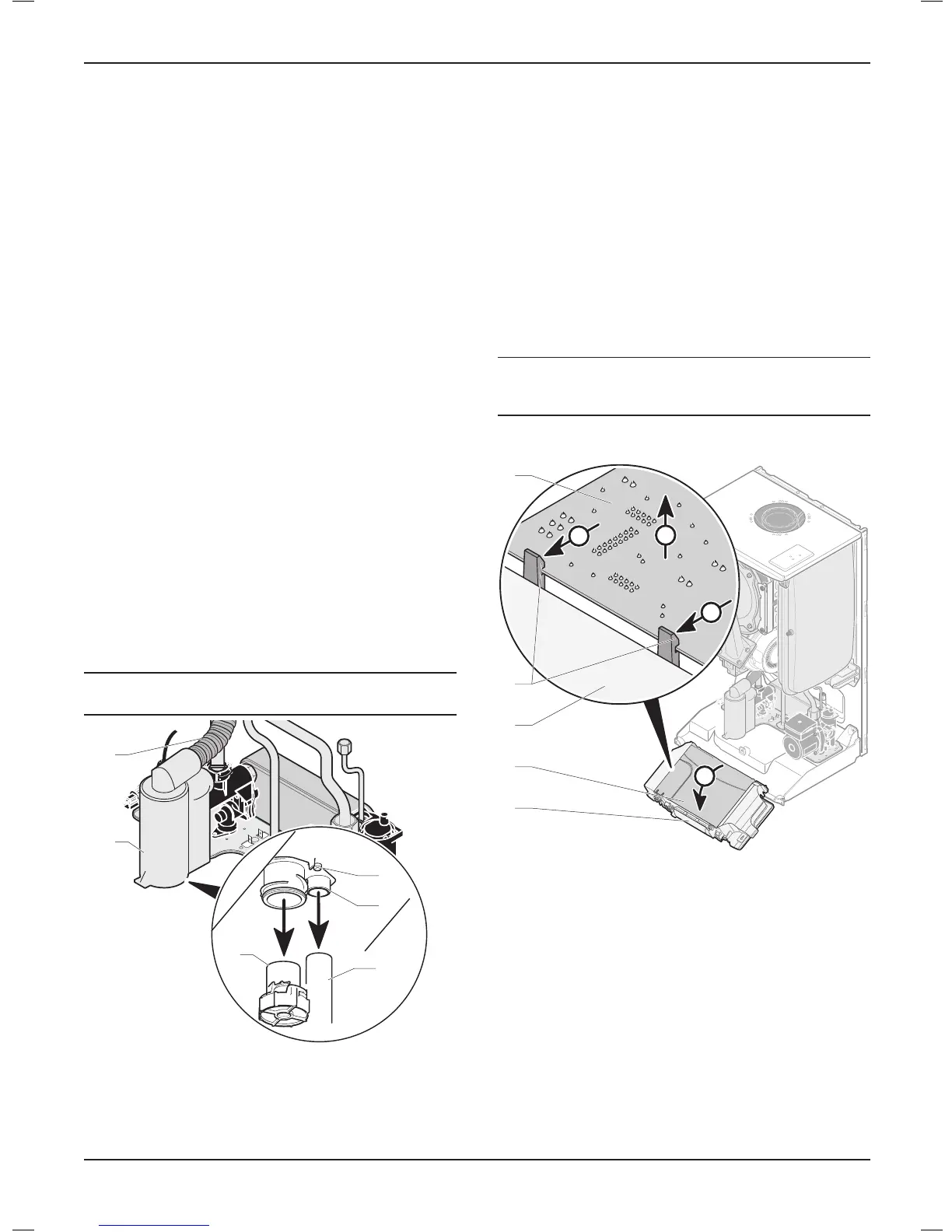
18.7 PCB
i
IMPORTANT:
When replacing the board refer to instructions supplied
with the spare part.
18.7.1 Main PCB
A
B
B
C
4
3
1
2
1
Key
1 Control panel
2 Rear panel
3 Retainings clips
4 Main PCB
• Remove the 24V and 230V connections.
• Remove the rear panel (2).
• Ease back the two PCB retaining clips (3) and withdraw the
PCB from the retaining lugs.
• Remove the electrical connections to the PCB (appliance
interface cable).
• When retting the rear panel, ensure the leads are not trapped.
MAINTENANCE
- 44 -
 Loading...