0020140413_01 - 09/12 - Glow-worm
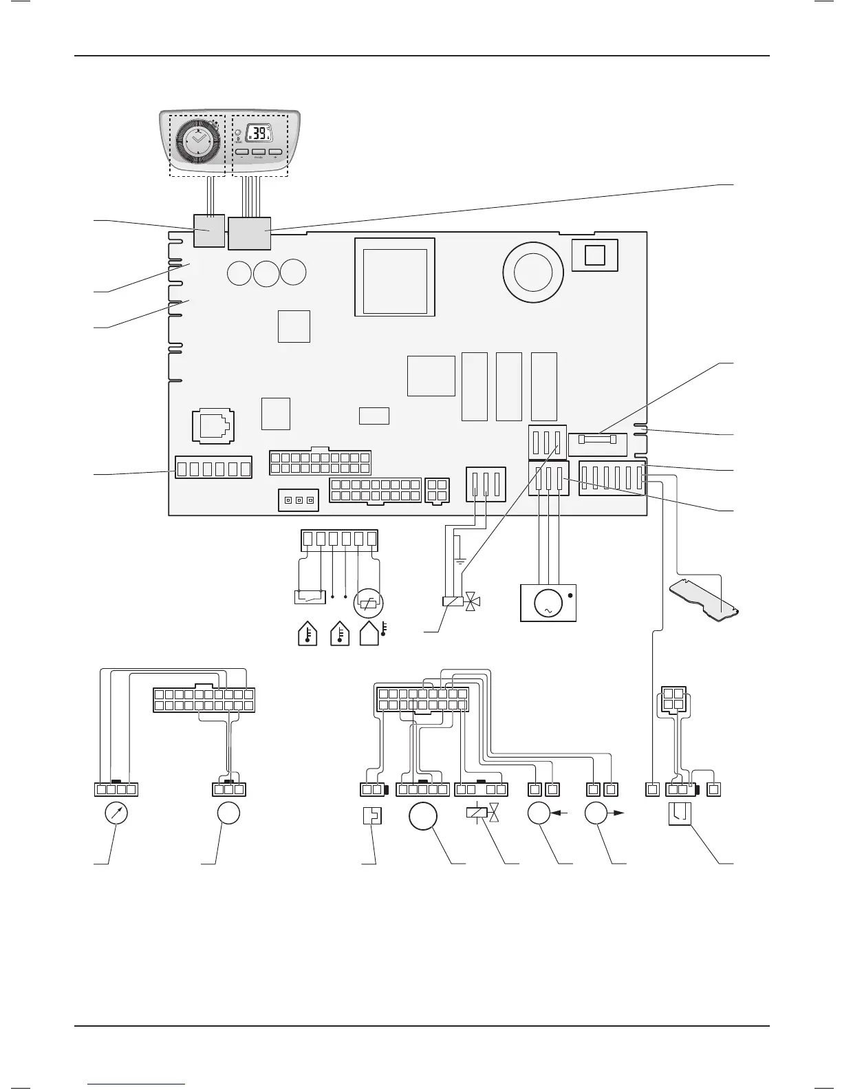
10.6 Wiring diagram
1
10
2
11
3
12
4
13
5
14
6
15
7
16
8
17
9
18
1 2
3 4
10 9 8 7 6 5 4 3 2 1
1920 18 17 16 15 14 13 12 11
M
Green/Yellow
D
M
TT
NTC
Ebus
24 V
INTERFACECL
X2
X30
X90
X32
X40
X51
X31
X21
X13
230 VAC
LN
X1
X101
FUS
X14
X20
X17
X17
X15
1 2 3
10 9 8 7 6 5 4 3 2 1
1920 18 17 16 15 14 13 12 11
34 2 1
X2
1 2 345 2 1 1 11 1...89 2 1
1
10
2
11
3
12
4
13
5
14
6
15
7
16
8
17
9
18
X20
1 2
3 4
1
1 2
1
X21
Green/Yellow
Green/Yellow
18 17 16
1
2
3
4
9
6
5
8
7
1011121314
15
Key
1 Control accessories connector
2 Reserved for future use
3 Location for external accessories (condensate pump and options
board)
4 Internal timer
5 User interface
6 Fuse 2A
7 Connector for 230 V option
8 Main supply 230V
9 Pump
10 Combinedsparkandamerecognitionelectrode
11 Heating outlet temperature sensor
12 Heating return temperature sensor
13 Gas valve
14 Fan
15 Threewayvalve
16 Thermal fuse
17 Waterowsensor
18 Water pressure sensor
INSTALLATION
- 20 -
 Loading...