0020140413_01 - 09/12 - Glow-worm
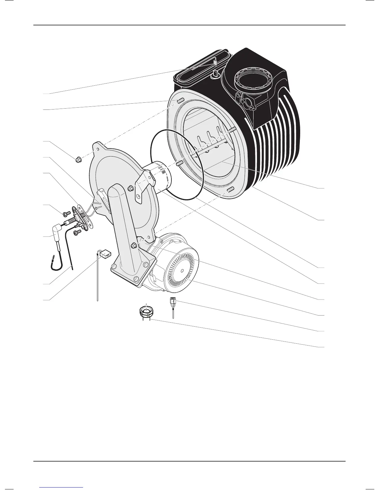
17.8 Combustion block
10
11
12
13
14
15
16
17
1
2
4
3
5
6
7
8
9
Legend
1 Gas valve connection
2 Grounding cable
3 Spark electrode inlet
4 Sparkelectroderetainingscrew.
5 Spark electrode gasket
6 Spark electrode
7 Burner retaining nut
8 Burnerretainingscrew
9 Thermal fuse connection
10 Coil
11 Heat exchanger
12 Burner door seal
13 Burner
14 Gas valve
15 Fan
16 Fan connection
17 Gas pipe
17.8.1 Spark electrode
• Disconnect the electrode inlet (3) and the grounding cable (2).
• Remove the 2 spark electrode retaining screws (4).
• Carefully remove the electrode from the combustion chamber.
• Check that the extremes of the electrode (6) are not damaged.
• Clean away any accumulation of dirt and check that the
distance between the two electrodes is between 3.5 and 4.5
mm.
• Check that the gasket (5) is not damaged. Replace if necessary.
MAINTENANCE
- 37 -
 Loading...