Supplied By www.heating spares.co Tel. 0161 620 6677
13
4.4 Bypass
The boiler is fitted with an adjustable automatic bypass.
Diagram 4.2 shows the pump head remaining for the heating
system depending on the bypass setting and the speed
setting of the pump, see section 11 Commissioning.
Ensure that under no circumstances does the flow rate drop
below the figure specified, refer to table 3 and section 11.6.
The installation of the boiler must comply with the
requirements of the current issue of BS6798, in Ireland,
refer also to the current edition of I.S.813 “Domestic Gas
Installations”.
In GB it is necessary to comply with the Water Supply (Water
Fittings) Regulations 1999 (for Scotland, the Water Byelaws
2000, Scotland).
To comply with the Water regulations your attention is drawn
to: The Water Regulations guide published by the Water
Regulations Advisory Service (WRAS) gives full details of the
requirements.
In IE the requirements given in the current edition of I.S.813
“Domestic Gas Installations” and the current Building
Regulations must be followed.
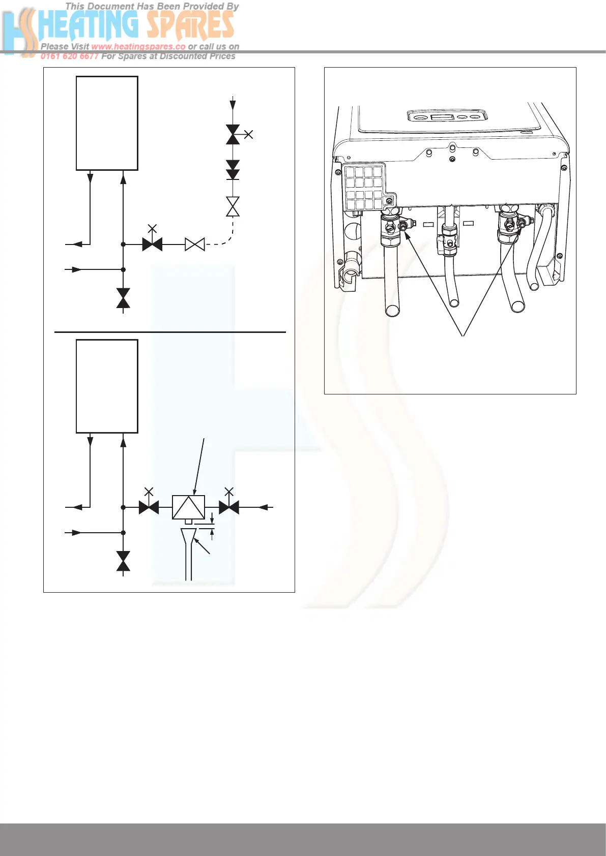
4.5 Filling the Sealed System
Provision for filling the system at low level must be made, see
diagram 4.3. There must be no permanent connection to the
mains water supply, even through a non-return valve.
NOTE: It is important that fittings used for connection
to potable water comply with the water undertakings
requirements.
4.6 Water Treatment
In the case of an existing system, it is ESSENTIAL that prior
to installing the new boiler the system is thoroughly flushed.
For optimum performance after installation of a new system,
the boiler and its associated central heating system should
also be flushed. Flushing should be carried out in accordance
with BS7593: 1992 using a cleanser such as Sentinel X300
or X400, Fernox Restorer or Salamander corrosion guard
cleaner.
For long-term corrosion protection, after flushing, a suitable
inhibitor should be used, refer to the current issue of BS
5449 and BS 7593 on the use of inhibitors in central heating
systems. Examples are Sentinel X100 Fernox Protector or
Salamander corrosion guard inhibitor.
4.7 Draining Points
Draining taps must be provided at the lowest points of the
system, which will allow the entire system to be drained.
Drain points for the appliance are provided at the positions
shown in diagram 4.4.
Diagram 4.4
13034
4 Heating System
TEMPORARY
CONNECTION
HOSE
UNION
HOSE
UNION
SUPPLY
PIPE
CONTROL
VALVE
CONTROL
VALVE
DOUBLE
CHECK
VALVE
BOILER
RETURNFLOW
HEATING
CIRCUIT
DRAIN
POINT
SUPPLY
PIPE
AIR GAP
TUNDISH
CONTROL
VALVE
CONTROL
VALVE
TYPE CA BACKFLOW
PREVENTION DEVICE
BOILER
RETURNFLOW
HEATING
CIRCUIT
DRAIN
POINT
Method 1
Method 2
Diagram 4.3
11593

 Loading...


