Supplied By www.heating spares.co Tel. 0161 620 6677
14 Replacement of Parts
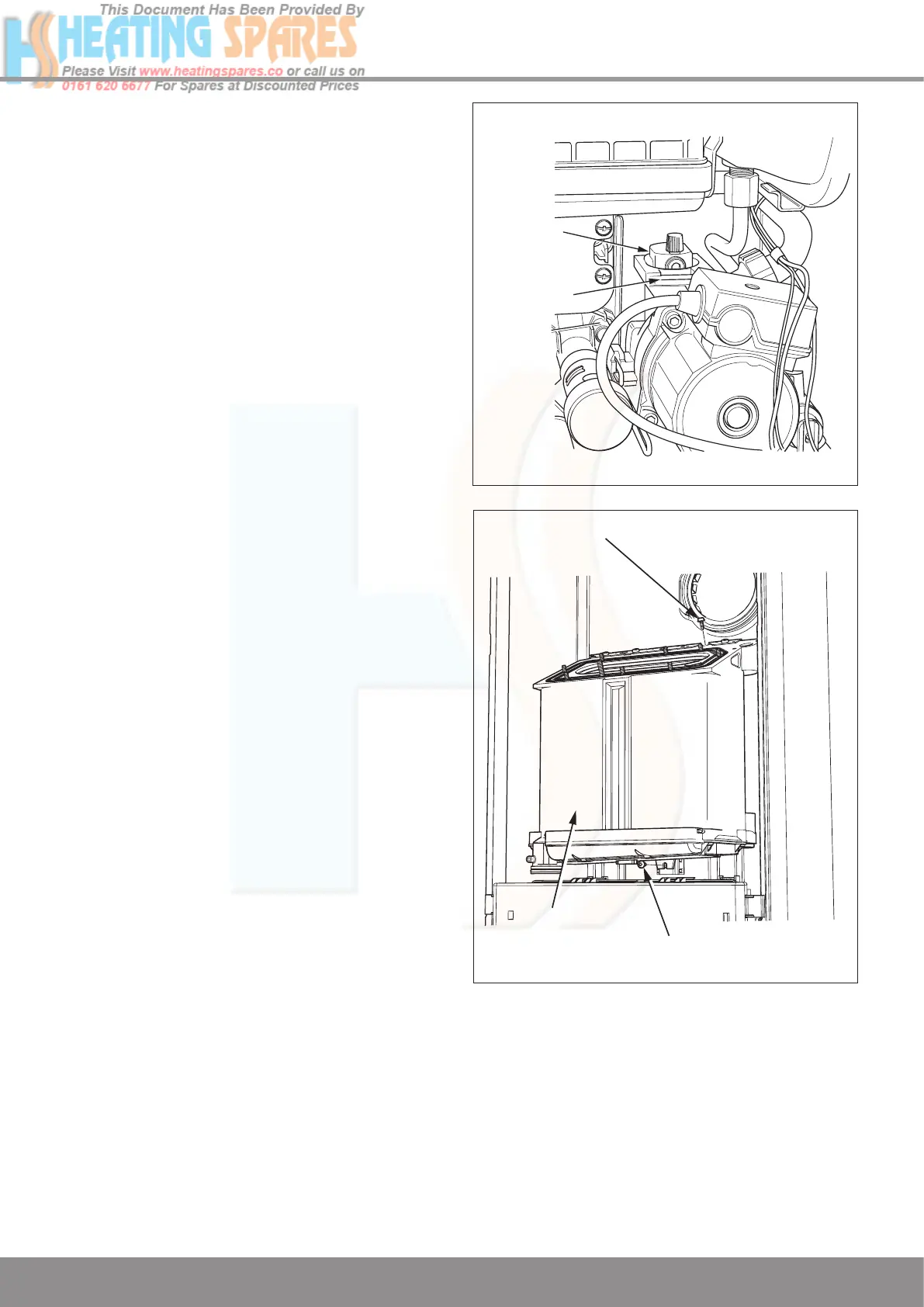
Diagram 14.8
14.19 Automatic Air Vent
For access, refer to section 14.1.
Refer to section 14.2 and drain the boiler heating circuit.
Refer to diagram 14.8.
Remove the retaining clip to release the automatic air vent.
Fit the new automatic air vent and ‘O’ ring ensuring the vent
cap is left loose.
Refill, vent and pressurise the boiler and check for leaks.
14.20 Heat Exchanger
For access, refer to section 14.1.
Remove silencer front, flue hood, gas valve / burner assembly,
spark electrode lead, burner and condense trap.
Refer to section 14.2 and drain the boiler heating circuit.
Remove the retaining clip from the flexible hose connection
into the brass elbow on the lower left hand side of the heat
exchanger. Detach the flexible hose.
Remove screws securing the heat exchanger, one on top and
one underneath the heat exchanger, see diagram 14.9.
Undo the knurled nut at the right hand side of the hydroblock.
Remove the retaining clip from the flanged elbow at the right
hand bottom of the heat exchanger. Remove the flow pipe.
Lift up heat exchanger slightly to disengage it from its hanging
bracket.
Remove the heat exchanger by pulling forward and tilting
backwards to ease removal complete with sump, return pipe
and flanged elbows.
AUTOMATIC
AIR VENT
RETAINING
CLIP
13066
Z
HEAT
EXCHANGER
SECURING SCREW
SECURING
SCREW
Diagram 14.9
12812

 Loading...


