Supplied By www.heating spares.co Tel. 0161 620 6677
39
12 Servicing
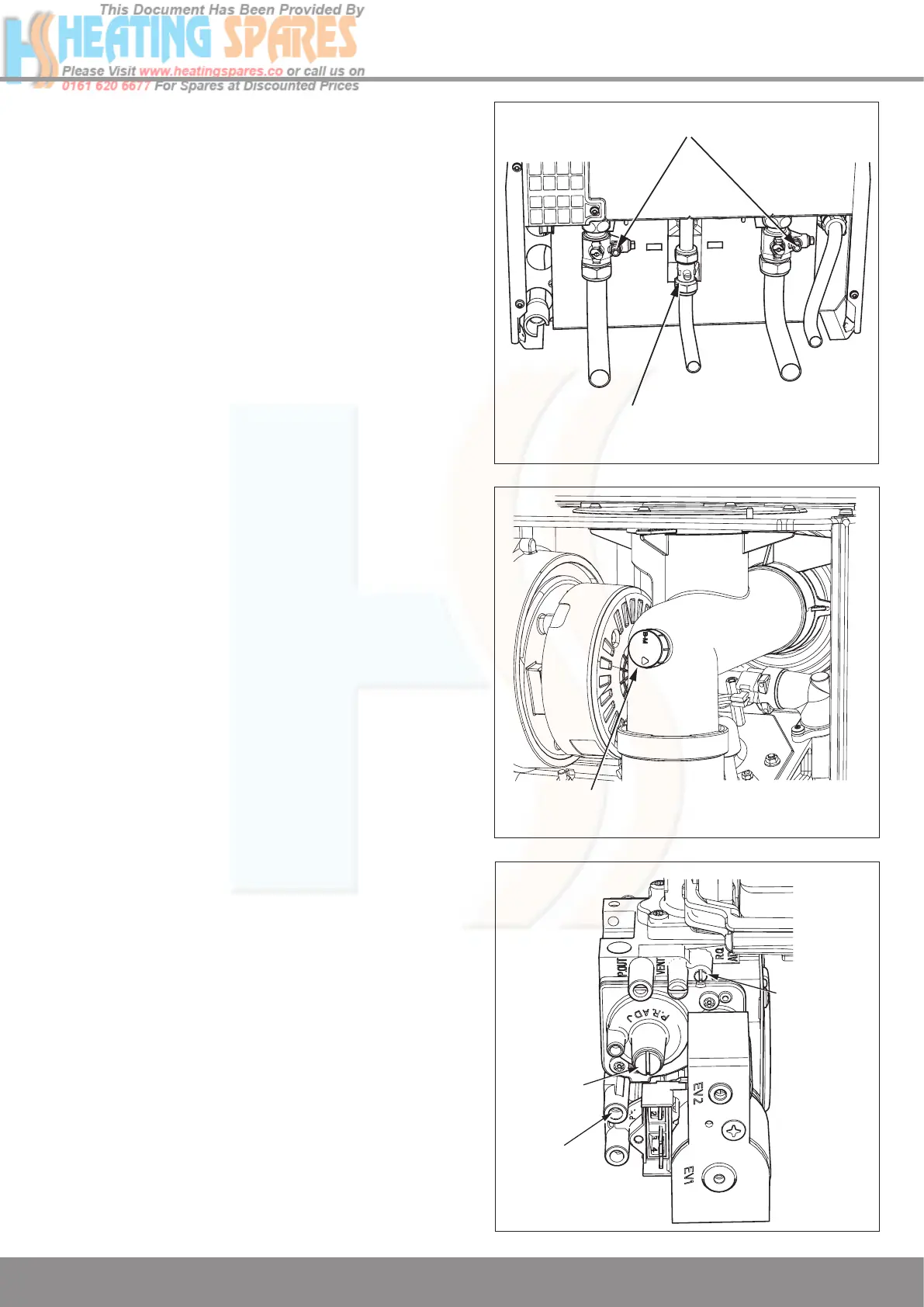
Diagram 12.1
Important Notes
To ensure the continued efficient and safe operation of the
boiler it is recommended that it is checked and serviced at
regular intervals. The frequency of servicing will depend upon
the particular installation and usage, but in general once a
year should be enough.
It is the Law that any servicing is carried out by a competent
person.
When replacing a part on this appliance, use only spare parts
that you can be assured conform to the safety and perform-
ance specification that we require. Do not use reconditioned
or copy parts that have not been clearly authorised by Glow-
worm.
Before commencing with a service or replacement of parts
the boiler should be isolated from the electrical supply and the
gas supply should be turned off at the gas service cock, see
diagram 12.1.
Testing Flue Gases: If any doubt exists that the flue prod-
ucts are not exhausting correctly, investigate by use of a gas
analyser (FGA).
Measurement of the products of combustion can be achieved
by removing the front panel as described in section 12.1 and
then connecting a probe to the combustion analyser test point
on the flue elbow, refer Combustion Check.
IMPORTANT NOTE: Products of combustion will be dis-
charged when the cap is removed. It is important to replace
the cap immediately.
Combustion Check
A combustion check should not be necessary unless a gas
carrying component has been replaced or the combustion
setting is suspect.
Connect a CO
2
combustion analyser to the test point, see
diagram 12.2.
Turn on the gas service cock, see diagram 12.1.
Turn on the electrical supply, the appliance will begin the igni-
tion sequence.
A competent person only should carry out any adjust-
ment to the gas valve, refer to diagram 12.3.
Monitor the combustion reading and at max rate the read-
ing should be 9.3% ± 0.5.
If adjustment proves necessary then proceed as follows:
Press the “reset” button on the controls fascia, release and
immediately press and hold in the “+” button. After approxi-
mately 5 seconds “Hi” will be displayed. Pressing the mode
button when “Hi” is selected will force the boiler to maximum
rate, the display will flash between “Hi” and the “default dis-
play” this will indicate the boiler has been forced to maximum.
Adjust the maximum rate CO
2
with the throttle to 9.3%. (Ro-
tate anti-clockwise to increase).
To exit the check sequences press the “mode” and “+” buttons
simultaneously, this will reset the boiler to the default display.
13044
COMBUSTION ANALYSER
TEST POINT
13028
Diagram 12.2
OFFSET
OFFSET
PRESSURE
THROTTLE
12776
Diagram 12.3
GAS SERVICE COCK
DRAIN POINTS

 Loading...


