Supplied By www.heating spares.co Tel. 0161 620 6677
9 Flue Preparation and Installation
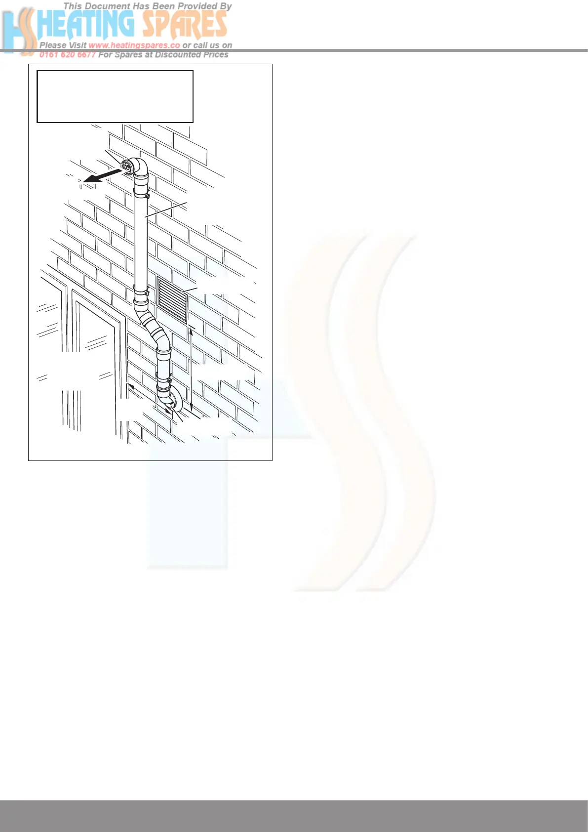
Diagram 9.26
9.20 Plume Management Kit
The Plume Management Kit: Part No. A2044100 (white) or
A2044000 (black) can be used to overcome many site issues.
The Plume Management Kit will fit to the Top Horizontal Tel
-
escopic, Rear Horizontal Telescopic and Standard Horizontal
Flue. This enables the flue products to exhaust further away
from the boiler, thereby reducing the impact of pluming 6M.
The flue air inlet can be sited closer to doors, opening win
-
dows and air bricks, see diagram 9.26.
The maximum length of the Plume Management Kit must NOT
exceed 6m with a horizontal concentric flue length of 2m max.
For each 90
o
bend or 2 x 45
o
bends the maximum length of the
Plume Management Kit must be reduced by 1m.
For more information contact Glow-worm, refer to page 2.
The Plume Management Kit is supplied with installation
instructions.
FLUE
OUTLET
FLUE
PRODUCTS
AIR INLET
PLUME
MANAGEMENT
KIT
75mm. MIN.
AIR BRICK
OPENING
WINDOW
OR DOOR
100mm.
MIN.
IMPORTANT: The flue outlet must
not be positioned within 300mm
from an opening, air brick or
opening windows.
12997

 Loading...


