Supplied By www.heating spares.co Tel. 0161 620 6677
41
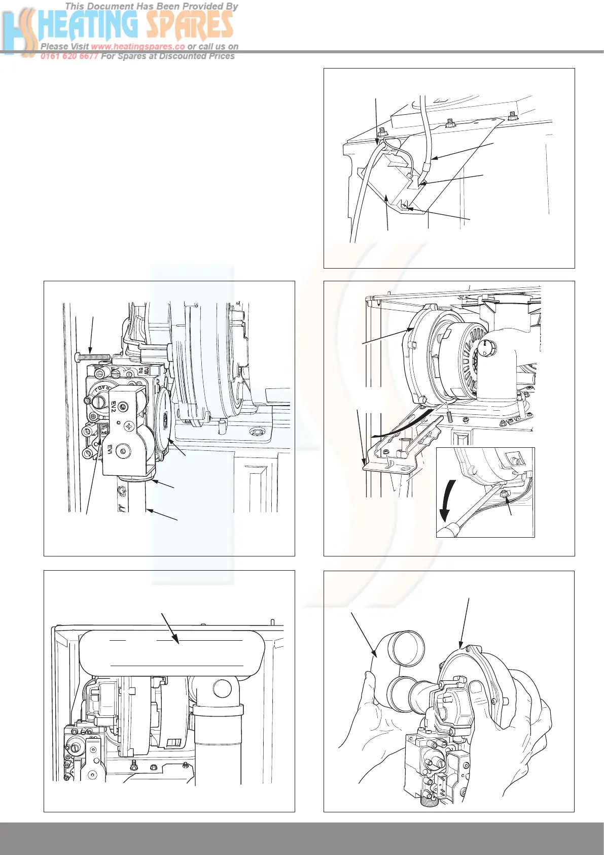
12 Servicing
12.3 Burner
Disconnect the gas supply at the gas valve and electrical
connections, see diagram 12.6.
The Silencer (front) is a push fit, so there is no need for tools
to remove or fit, see diagram 12.7.
Release the igniter unit support bracket, see diagram 12.8.
Remove the fan retaining bracket.
To ease removal of the securing nut from the fan retaining
bracket, a flat bladed screwdriver can be used in the position
shown and gently levered down as indicated, see diagram
12.9.
Remove the fan and gas valve assembly.
The silencer (rear) is a push fit so no tools are required for its
removal or fitting, see diagram 12.10.
IGNITER
UNIT
SECURING
SCREWS (2)
SPADE
CONNECTOR
ELECTRICAL
CONNECTIONS
IGNITION
LEAD
Diagram 12.8
12662
GAS
VALVE
GAS
PIPE
ELECTRICAL
CONNECTION
(removed)
SECURING
SCREW (3)
TUBING
NUT
Diagram 12.6
12664
Diagram 12.7
13128
12814
SILENCER
REAR
FAN/GAS VALVE
ASSEMBLY
Diagram 12.10
13007
FAN
SECURING
NUT
FAN
RETAINING
BRACKET
Diagram 12.9

 Loading...


