10
2000221595
AB
C
D
E
2
3
6
4
7
5
8
9
1
12
14
13
15
16
18
17
19
20
22
21
23
11
25
24
10
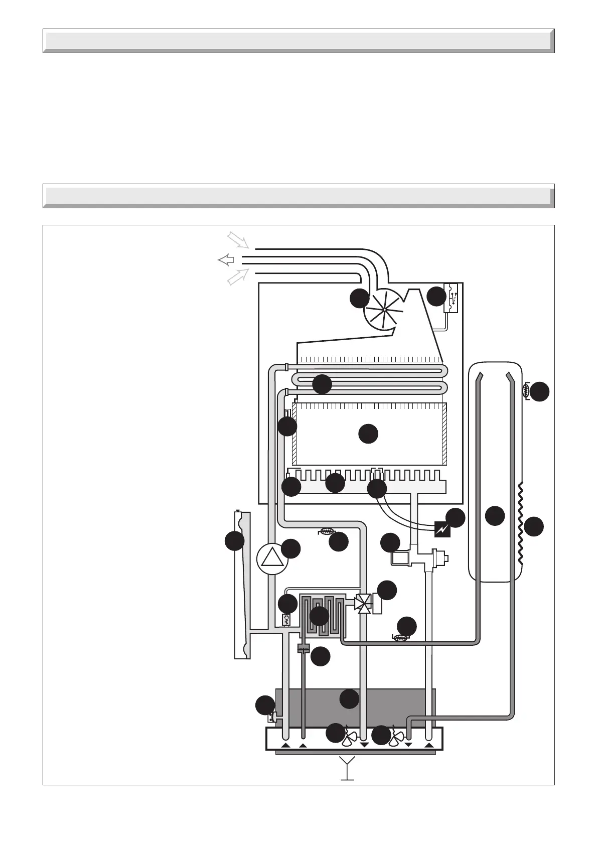
Diagram 5.1
4 Domestic Hot Water System Design
• Copper tubing or plastic hep
2
o may be used for the domestic
hot water system. Unnecessary pressure losses should be
avoided.
• A flow restrictor limiting the flow through the boiler to a
maximum of 12 l/min is fitted to the boiler.
• The boiler will operate with a minimum supply pressure of 0,7
bar, but under reduced flow rate. Best operating comfort will be
obtained from a supply pressure of 1 bar.
'Hard Water Areas'
In areas where the water is 'hard', more than 200mg/litre, it is
recommended that a proprietary scale reducer is fitted in the
cold water supply to the boiler.
1 - Domestic thermistor
2 - Three way valve
3 - Gas valve
4 - Ignition module
5 - Heating element
6 - Micro accumulation vessel
7 - Burner
8 - Ignition electrode
9 - Combustion chamber
10 - Micro accumulation vessel thermistor
11 - Main heat exchanger
12 - Air pressure switch
13 - Heating safety valve (3 bar)
14 - Electronic control (PCB)
15 - Domestic water flow sensor
16 - Bypass
17 - Domestic heat exchanger
18 - Pump
19 - Expansion vessel
20 - Heating thermistor
21 - Overheat safety thermostat
22 - Flame sense electrode
23 - Fan
24 - Domestic safety valve (10 bar)
25 - Loss of water sensor
A - Heating return
B - Cold water inlet
C - Heating flow
D - Domestic hot water outlet
E - Gas
10026
5 Boiler Schematic
 Loading...