26
2000221595
17 Fault Finding
Fault finding must be carried out by a competent person.
WARNING. Always isolate the boiler from the electrical supply
before carrying out any electrical replacement work.
On completion of a fault finding task that has required the
disconnection and making of electrical connections then check
for earth continuity, polarity and resistance to earth must be
carried out.
If any gas-carrying components are disturbed, removed or
replaced it will be necessary on completion to check for gas
soundness with leak detection fluid.
Before trying to operate the boiler make sure that :
• All gas supply cocks are open and that the gas supply has
been purged of air.
• There is a permanent mains supply to the boiler.
• The heating system pressure is at least 1 bar.
• The fuse on the PCB is intact.
Preliminary electrical system checks, as outlined in a multimeter
instruction book, are the first checks to be carried out during a
fault finding procedure.
Should there be any doubt about the voltage supply to any of
the components, it is possible to carry out a simple electrical
test to ensure all is operational in that area.
To carry out the electrical test, gain access to the main Printed
Circuit Board (PCB) , and measure the voltages according to
table 2.
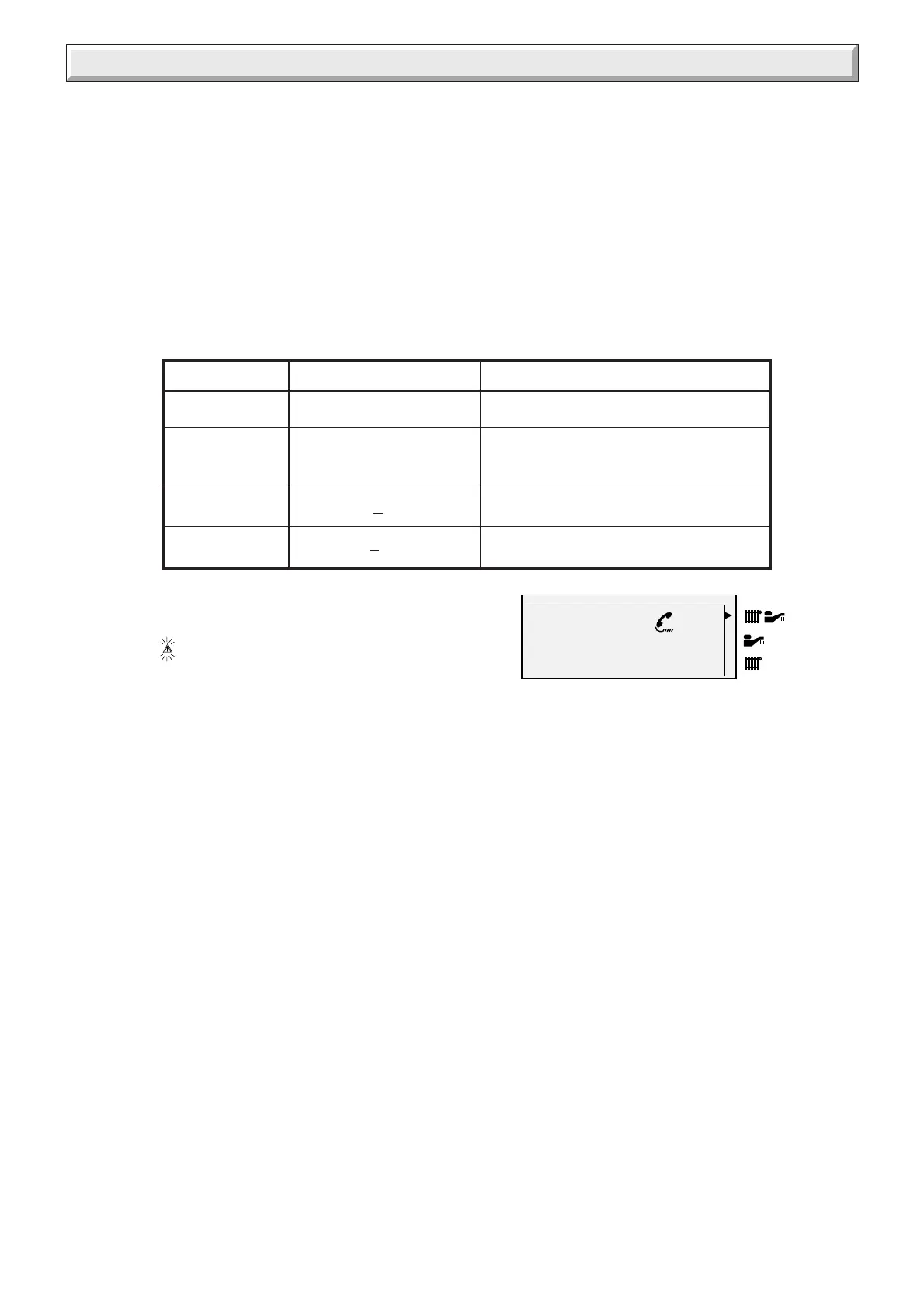
Table 2
Voltage Measured value Measuring point
230 Volt 230 V AC Between terminals H8.1 and H8.2
24 Volt maximum 33V DC Between terminals B2.4 and B2.7
minimum 20V DC
15 Volt 15V
+
0.5V Between terminals B2.4 and B2.2
Display 5V
+
0.5V Between terminals B2.4 and B4.2
09 FF
Sec 052
A fault code is displayed on the left hand side of the LCD display, whilst at the same time, the letters appear with a
telephone symbol.
Thermistor values
The following table applies to the central heating,
domestic hot water and storage vessel thermistors:
Temperature (°C) Resistance (Ω)
0 ......................................32565
5 ......................................25345
10 .....................................19875
15 .....................................15700
20 .....................................12500
25 .....................................10000
30 ......................................8060
35 ......................................6535
40 ......................................5330
45 ......................................4370
50 ......................................3605
55 ......................................2989
60 ......................................2490
65 ......................................2085
70 ......................................1755
75 ......................................1480
80 ......................................1260
85 ......................................1070
90....................................... 920
95....................................... 785
100...................................... 680
System pressure sensor
The resistance of the sensor at various pressures is
as follows :
0 bar ...................... between 280 Ω and 320 Ω
1 bar ...................... between 195 Ω and 220 Ω
3 bar ...................... between 93 Ω and 143 Ω
The In-board fault diagnostic system. Should a fault
occur on the boiler, the warning LED at the top of the
user display will illuminate and the LCD display will
indicate the precise area where the fault has occurred.
 Loading...