12
2000221595
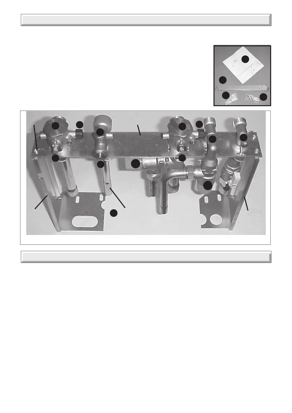
7 Fixing Jig Pack
The fixing jig is made up, from left to right, as follows:
A - Heating return fitting with isolating valve(v) and
drain knob (u).
B - Cold water inlet fitting with isolating valve (m)and
factory fitted flow regulator and filter (not shown).
C - Heating flow fitting with isolating valve (q), drain
knob (r) and safety valve (s1).
D - Domestic hot water outlet fitting with safety valve
(s2).
E - Gas fitting.
Diagram 7.1
8.1 Fixing jig
• Remove the contents of the fixing jig pack.
• Secure the left and right hand support brackets to the isolating
valve plate with the securing screws (4 OFF) supplied, see
diagram 7.1.
• Connect the six copper connections and sealing washers to
the isolating valves, see diagram 7.1.
• Heating system connections - Pipe diam. 22mm
• Hot water system connections - Pipe diam. 15mm
• Gas connection - Pipe diam. 22mm
• Domestic safety valve connection - Pipe diam.15mm
• Heating safety valve connection - Pipe diam. 15mm
8.2 Wall template
• Remove the wall template, follow the instructions given on the
wall template.
• Note: It is important the hanging bracket and service cock
8 Piping System Installation
v
A
B
m
C
q
D
r
E
u
s1
s2
COPPER
CONNECTIONS
AND WASHERS
(7 OFF)
H
G
F
K
J
THE FIXING JIG SHOWN ASSEMBLED
Other components within the fixing jig pack.
F - Hanging bracket
G - wall template
H - copper connections
J - sealing washers
K - sealant (putty)
RIGHT
HAND
SUPPORT
BRACKET
LEFT
HAND
SUPPORT
BRACKET
ISOLATING
VALVE PLATE
SCREW
(4 OFF)
bracket are fitted to a flat and true wall area for correct alignment
with the boiler. If this is cannot be achieved it is acceptable to
pack out the service cock bracket to obtain the correct alignment.
• Position the wall template, see diagram 8.1.
• Mark the position of the holes for the hanging bracket and jig.
• Drill, plug and fix the hanging bracket to the wall using suitable
screws.
• Check that the hanging bracket is level.
• Drill plug and fix the fixing jig to the wall.
• For horizontal flue system, mark the position for the flue hole
as follows:
8.3 Flue to rear of boiler
• Mark correct position of hole from template.
8.4 Flue to side of boiler
• Mark the horizontal centre line for the hole on the rear wall.
Extend the horizontal centre line to the side wall and mark the
vertical centre line of flue hole as shown in diagram 8.1.
9880
9959
 Loading...