Connect
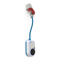
Never use the go-eCharger lying on its back; it may
collect water in the Type 2 outlet when it rains.
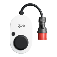
Connect the go-eCharger to a suitable power source
- at best directly to a CEE 16 A socket (go-eCharger
HOME+ 11 kW) or a CEE 32 A socket (go-eCharger
HOME+ 22 kW) or with an adapter to a
corresponding other power source.
Page 12
Commissioning
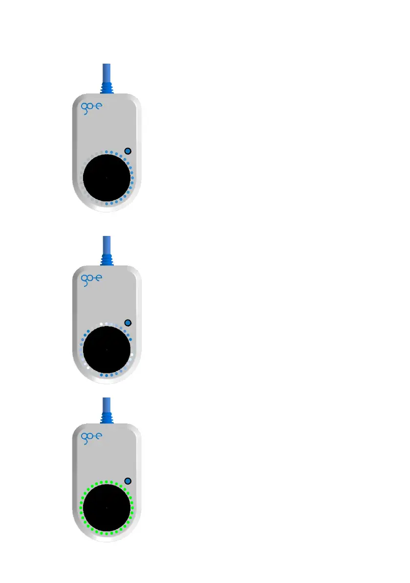
After an initial self-test in which the LEDs shine in
rainbow colours, the LEDs light up blue in the
number of the strength of the preset charging current
(in amperes).
The button (5) can be used to select between 6 A and
16 A (go-eCharger HOME+ 11 kW) or between 6 A
and 32 A (go-eCharger HOME+ 22 kW). The levels of
the selection can be individually adjusted in the app.
It does not matter whether the go-eCharger is
connected in one or three phases.
Charging process
Now insert your type 2 cable into the charging unit.
All LEDs light up yellow during the test. The charging
process is started with a clicking sound in the
charging unit and is indicated by switching the LEDs.
During charging, the LEDs run clockwise around the
charging socket. The number of "tails" corresponds
to the number of connected phases while the rotation
speed depends to the charging current.
Exit charging process
The charging process is terminated by the vehicle.
This is usually the case when the vehicle's battery is
fully charged. The cable remains locked (default
settings) in the type 2 socket after the charging
process is complete until it is removed from the
vehicle (theft protection).
If you want to interrupt charging prematurely, you can
do this via the function of your vehicle ("Cable
unlocking") or via the app ("Activation").
Page 13
The go-eCharger has a built-in RCD protection device with DC
current detection (30 mA AC and 6 mA DC). Therefore an
upstream residual current circuit breaker (RCCB) type B is not
necessary. The circuit to which the go-eCharger is connected has
to be independently of this fitted with an RCCB type A and a
miniature circuit breaker (MCB) according to the the following
specification:
Ÿ Characteristic B and C is permissible
Ÿ Connection 16/32 A three-phase = 3- or 4-pole MCB for 16/32 A
Ÿ Connection 16/32 A single-phase = 2-pole MCB for 16/32 A
The device can be installed indoors or outdoors. Provide a power
supply. If a three-phase socket is available, insert the charging unit
onto the wall mount and the plug of the charging unit into the
socket to determine the best positioning of the wall bracket. Also
use this as a template for marking the drill holes. Use a spirit level
to align the wall mount.
Use the screws and dowels supplied to attach the wall bracket.
Make sure that there are no distortions on the surface. If the wall
bracket warps, it may not be possible to attach the device. Use
spacers to compensate for any unevenness in the wall.
If there is no three-phase current connection, have the three-
phase current socket installed by a qualified electrician. This
qualified person has a recognised electrical engineering
qualification which enables him/her to carry out all electrical
engineering work in accordance with the applicable national
regulations. You can achieve a comfortable height for the charging
box by having the three-phase socket installed approx. 170 cm
above the floor.
If necessary, attach the supplied U-piece for optional cable
securing with the screw and dowel still present so that you can
lay the connection cable leading to the CEE socket in the U-
piece. The cable is then secured with a padlock, which is not
included in the scope of delivery.
Mounting of go-eCharger HOME+