IM067B2 – June 2010
4
2. INSTALLATION INSTRUCTIONS
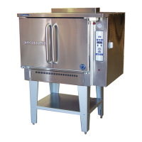
PRE-INSTALLATION OF THE X500
Assemble legs to X500A
To assemble the legs place two pieces of timber approx. the depth of the unit covered
with plastic on the floor beside the unit. Tip the unit over onto these two pieces of
timber exercising care not to jam your hands.
Then proceed to bolt the legs onto each corner after the legs are in place bolt the metal
shelf into place which helps align the legs. When this is complete then carefully raise
the unit up onto its legs.
Levelling of X500A
X500A have a levelling adjustment at the bottom of each leg. Start with this adjustment
screwed all the way in. With a spirit level placed on an oven rack check and level side
to side first, then front to back, this is important as floors can be out 75mm of level.
ELECTRICAL CONNECTION
The electric motor, indicator light and related switch, are all connected to a terminal
block found at the top of the oven. The supply cord must be plugged into a properly
ground three-prong receptacle. Do not cut or remove the grounding prong from the
plug.
Normal factory connections are made for operation on 240 volt AC50 cycle.
VENTILATION
Proper ventilation is essential for good oven operation. When a hood is used as means
of ventilation, it should extend at least 150mm beyond all sides of oven (except against
a wall, if it is a wall installation). Oven must be 50mm off wall.
IMPORTANT
If the oven is to be “built-in”, adequate air space for proper venting of the motor must be
provided at the bottom and top of the unit, or WARRANTY WILL BE VOID.