4
DESCRIPTION
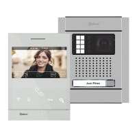
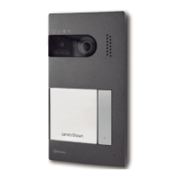
ART 4/G2+MONITOR
H
I
J
H
H
H
SA
GND
HZ
HZ
ON
1 2 3 4 5 6 7
8
BUS
A
D
B
C
E
G
F
BUS
12210430 V0Product Version: 4
MONITOR 4 ” ART 4/G2+.3
GOLMAR S.A. C/ Silici, 13 08940-SPAIN
WARNING
To prevent fire or electric shock, do not
expose this device to rain or moisture
To prevent electric shock, do not remove cover.
CAUTION
No user serviceable parts inside.
Refer servicing to qualified service personnel
MADE IN CHINA
SA
GND
HZ
HZ
BUS
BUS
OFF = 0
DIP 1 to 5
DIP 8
Monitor address
EOL resistor
DIP 6,7
00 - Master
10 - Slave 1
01 - Slave 2
11 - Slave 3
ON = 1
ART4 G2+ monitor with V.03 and later.
*
*
*
Press to acces the recordings menu (standby monitor):
- The push button led will blink in white color indicating
that a photo/video is pending viewing. Pressing will
access the recordings menu.
- The push button led will blink in white color if the
function 'Doctor mode' is activated and it will turn off if
the function is deactivated.
B. Function buttons, access and selection of menu
functions.
- With the special code '0441' (Doctor mode) already
entered (see pp. 25 to 26), press the button for 5 sec.
to activate/ deactivate the function.
The function of each button is shown on the monitor
screen with an icon located just above each button
(see pp. 6 to 24).
Press to access 'Doctor mode' function (standby monitor):
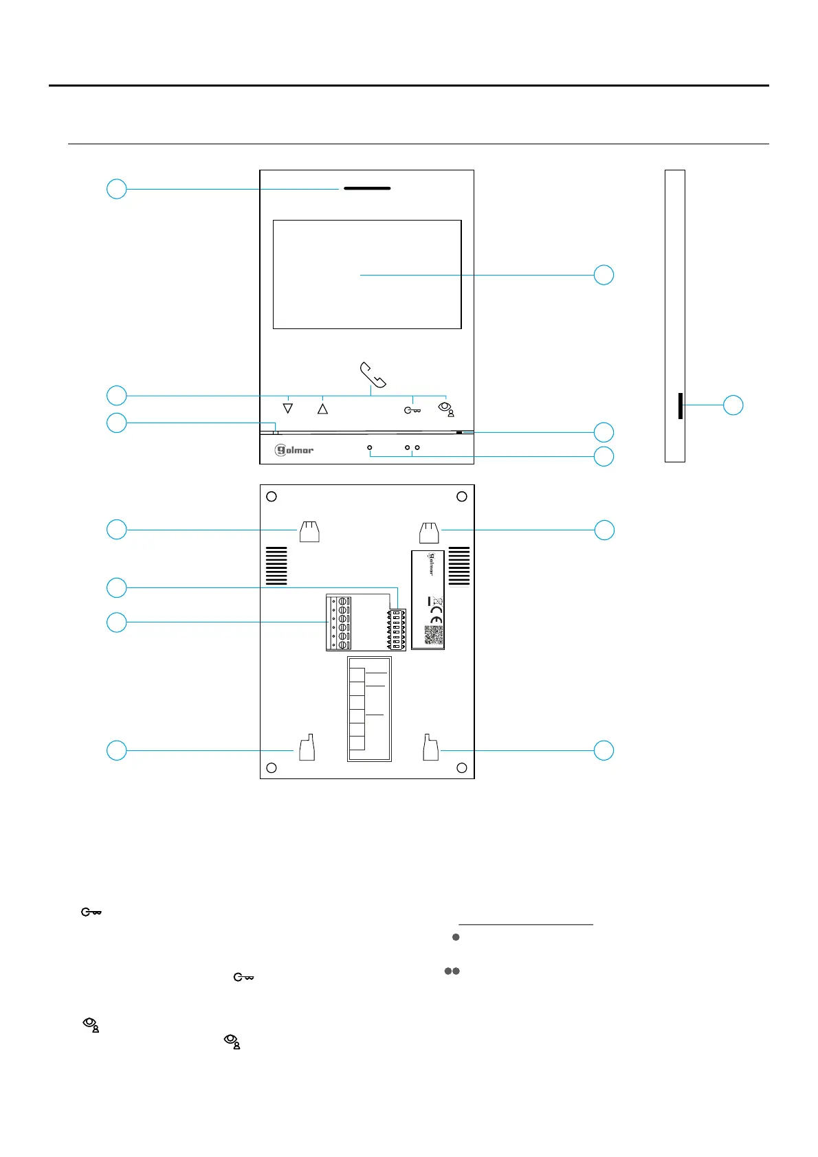
A. Speaker.
G. Micro SD card slot (not included).
C. LEDMonitor status :
Yellow ON: Standby without notification.
I. Configuration switches.
Above these raised dots is the 'Door opening' button.
Red ON: “Do not disturb” Mode a tivated.c
F. .Raised dots for the visually impaired people
H. Wall mounting connector fixing (x4).
D. 4.3" TFT colour screen.
In call :/communication
E. Microphone.
Type: MicroSD Class 10 from 4 to 128 .GB GB
J. Installation terminals.
Above this raised dot is the 'Start/ nd communication'
button.
E
 Loading...