51
WIRING DIAGRAMS
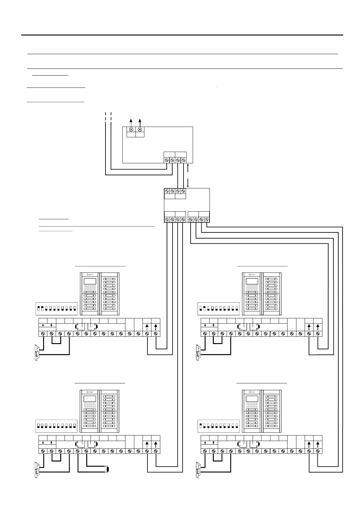
NEXA MODULAR G2+ AUDIO AND VIDEO DOOR ENTRY SYSTEM - BUILDING
BUSBUS
BUS BUS
D
C
B A
DPM- 2+G
AP
(1) (1)
Lock release
max. 12 Vdc/270mA.
Lock release
max. 12 Vdc/270mA.
Important: 52 .For a second a.c lock release connection, (see page )
(1)
(1)
(1)
Acces door panel 2
Acces door panel 1
Acces door panel 4 Acces door panel 3
BUS (M) BUS(PL)
FA-G2+
LN
NA2
+
AP-
C1
NA1
AP+
C2
AP+
GND
BUSBUS
Relé 2Relé 1
_
12Vdc
NC2
CCTV
1 2 3 4 5 6 7 8 910
ON
NA2
+
AP-
C1
NA1
AP+
C2
AP+
GND
BUSBUS
Relé 2Relé 1
_
12Vdc
NC2
CCTV
1 2 3 4 5 6 7 8 910
ON
(1) (1)
Lock release
max. 12 Vdc/270mA.
Lock release
max. 12 Vdc/270mA.
(1)
(1)
NA2
+
AP-
C1
NA1
AP+
C2
AP+
GND
BUSBUS
Relé 2
Relé 1
_
12Vdc
NC2
CCTV
1 2 3 4 5 6 7 8 910
ON
NA2
+
AP-
C1
NA1
AP+
C2
AP+
GND
BUSBUS
Relé 2
Relé 1
_
12Vdc
NC2
CCTV
1 2 3 4 5 6 7 8 910
ON
( )
*
( )
*
IMPORTANT:
Max. 1 'AP'.external door opening button
Installations of more than 2 access door panels (Golmar
d.c lock release):
1 'AP' button installed of the door panels of the
installation.
in only one
(2)
(2)
Video door entry system: , see pages to .
To the risers distributor of the buiding, see pages to
36 45
46 48
To the distributors (building floors)
Audio and Video door entry system with 4 access door panels, DPM- + door panels distributor GolmarG2 & d.c
lock release.
Mains
100~240Vac
Max. distance: 1m.
Audio door entry system: To electrical junction box for Bus connections ART 1/G2+ terminals of the buiding (see page 34).
To for risers of the building (see page 35).electrical junction box