oorpanel configuration.
D
The doorpanel has a microswitch (SW1) and two jumpers
(JP1and JP2) placed on the rear part of the doorpanel.
Loads the installation with a communications resistor. For a
proper system operation, activate this resistor only in the
closest doorpanel to the backbone installation or in the
general entrance doorpanel (if exists).
Allows to reset the installer PIN code to the factory default (see
page 83). Use this funtion only in case to forget this code.
With the system switched on, change the switch position to
reset the code and return it to the standby position.
Selects the volume of the doorpanel acknowledgment signals (call
in progress, system busy and door opened).
If after starting the system it´s considered that the volume is too
high, modify the switch position.
Switch to ON in case there´s any UNO monitor or telephone in
the installation. Activate only in the closest doorpanel to the
backbone installation or in the general entrance doorpanel (if
exists).
Switch to OFF when using any digital repeater RD-Plus/Uno.
Place both jumpers in COAX position to select
coaxial cable video transmission RG-59
(pages 115 to 116 .)
Place both jumpers in TP position to select twisted
pair video signal transmission CAT-5 (pages
117 to 118).
SW1
JP1/JP2
O
X
CA
P
T
O
X
CA
T
P
*Factory default
81
DOORPANEL INSTALLATION
82
DOORPANEL INSTALLATION
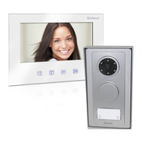
The doorpanel has two memory banks
to plug 256Kb memory modules in.
Each module allows to record the custom
text for a maximum of 968 users.
The system is delivered with one memory module
placed in the bank number 0 (BK0), where
the system configuration will be recorded.
IMPORTANT: in case of doorpanels with two memory modules,
don't change their bank position once they have been recorded.
BK0 bank module must always have a memory module plugged in.
IMPORTANT:
IMPORTANT:
emory banks.
M
omputer connection.
C
It's possible to program the doorpanel using a
computer through its RS-232C port.
An interface (not included) should be connected
to CN7 doorpanel connector. MEMEDIT software
(included with the interface) will allow to program
the doorpanel and to save a copy of each system.
In case of memory damage it will be possible
to restore the system configuration from the computer.
BK1BK1
BK0BK0
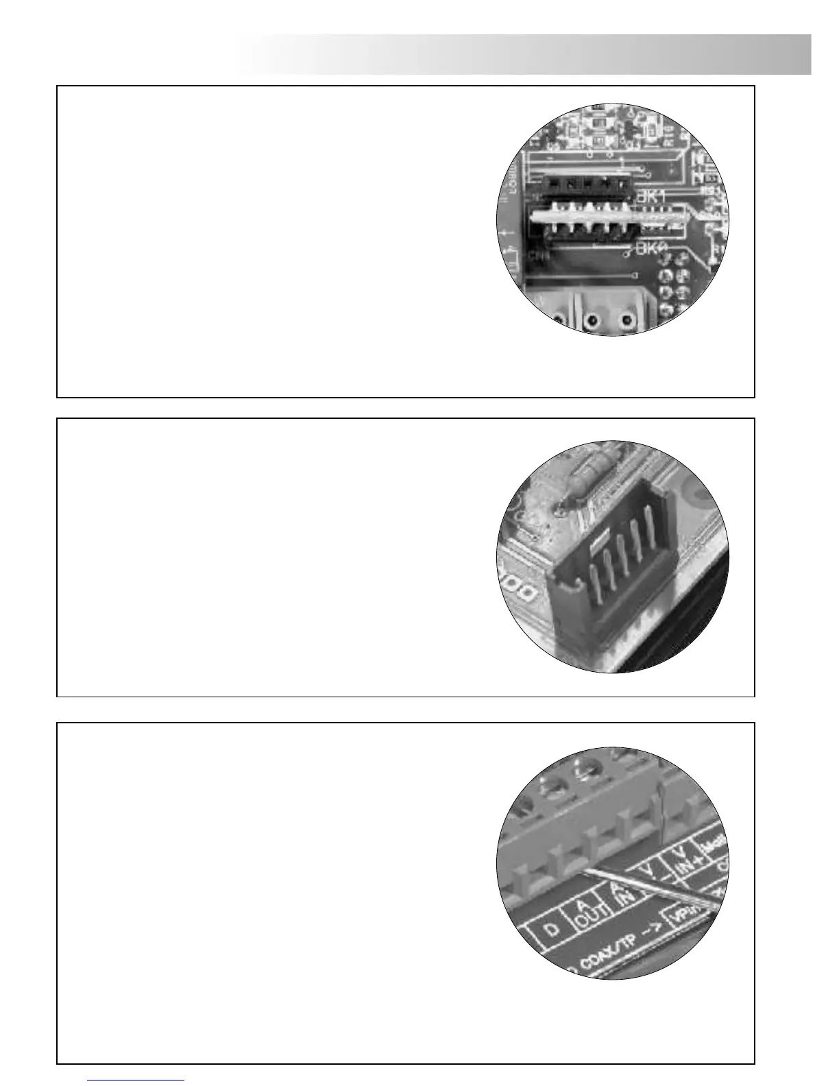
etachable connector.
D
The doorpanel has detachable connectors, that makes the
connection of the doorpanel to the installation much
more easier.
ÜDetach the connector by pulling with a slot
screwdriver.
ÜMake the proper connections according to the
installation diagrams on pages 115 to 125. Pay
special attention to follow the specified order for each
connection on the doorpanel silk.
ÜPlace again the connectors in the original position.