INSTALLATION DIAGRAMS
101
D3
BUS IN
PA PB
BUS OUT
HZ
End of
line
Insert a 120 ohm end of
line resistor in the last
distributor.
*
D4L-V2Plus
BUS IN
PA PB
BUS OUT
HZ
BUSD2D1 BUS D4
D3
End of
line
BUSD2D1 BUS D4
BUS IN
PA PB
BUS OUT
HZ
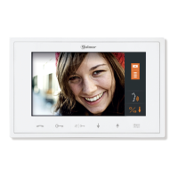
Platea V2Plus
BUS IN
PA PB
BUS OUT
HZ
*
R.1 20W
D4L-V2Plus
Configuring the end of
line in the last monitor.
Sw2
Platea V2Plus
Sw2
Platea V2Plus
Sw2
Platea V2Plus
Sw2
.
V
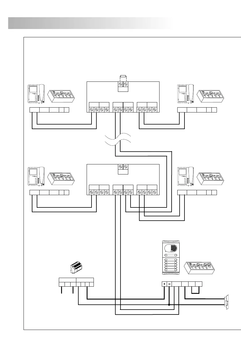
ideo door entry system with a 4 line distributor and d.c. lock release
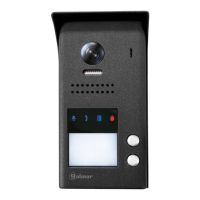
The installation diagram shows the connection of a video door entry system with one door
panel to access the building, with 4 line distributors and d.c. lock release D4L-V2Plus .
102
REMEMBER:
.
Using distributors with 4 outputs, the total number of elements in the
installation (monitors or telephones) must never exceed 32 units
SEC
PRI
+
0110230
FA-V2PLUS
- -
+
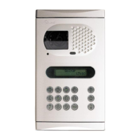
Main
Master door panel
CV1
+12
CV2
SW1
6
BUS
IMPORTANT: In the output to the monitor/telephone of a
.
distributor cannot be connected
another distributor
Sections chart
RAP-2150
Terminal
SECTIONS CHART
100m.
Door panel-Monitor
P.S. - Door panel
+, -
For greater distances contact our technical
support department.
BUS, D
50m.
Door panel - CV
50m.
2,5mm²
0,5mm²
CV1,CV2
2
Core max. electrical resistence to 20ºC
ELECTRICAL CHARACTERISTICS
19,5 W/Km
Nominal capacitance (core-core)
Characteristic impedance
VALUES
CONSTRUCTIVE CHARACTERISTICS
Class V
VALUES
Flexible bare copper conductor of 1mm (twisted)
AP-2150 cable characteristics.
R
45pf/m 10%
100 W 10%
+
-
+
-
**
**
**
**
**