5
ing the unit. If these units are installed in a removable
ceiling panel, ample space must be provided for servic-
ing the unit.
III. PIPING
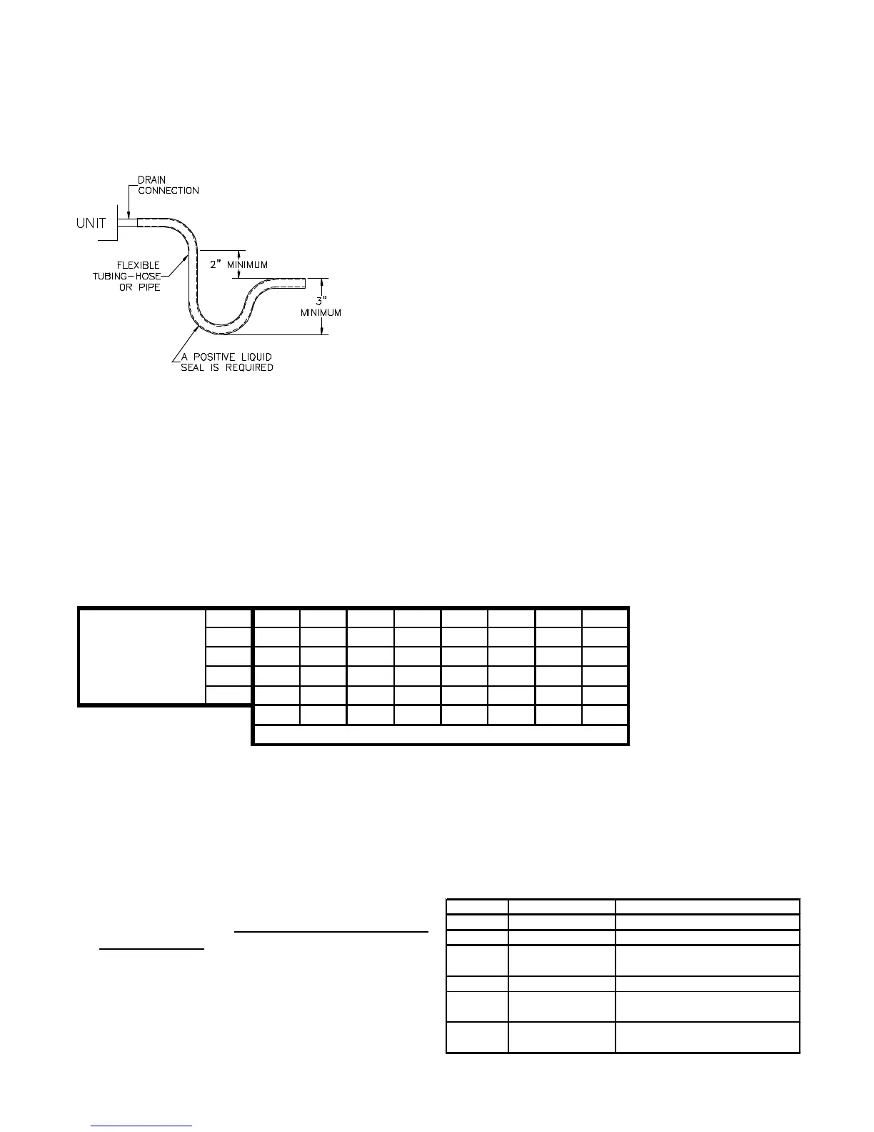
CONDENSATE DRAIN
FIGURE 3
The condensate drain connection of the evaporator is a half
coupling of 3/4" N.P.T. A trap must be provided to have
proper condensate drainage. See Figure 3.
Install condensate drain trap as shown. Use 3/4" drain
connection size or larger. Do not operate without trap.
Unit must be level or slightly inclined toward drain.
IV.ELECTRICAL WIRING
GENERAL
All wiring should be made in accordance with the
National Electrical Code in the U.S.A. Determine the
availability of sufficient power to operate the unit. The
voltage at the power supply should be checked to make
sure it corresponds to the unit’s RATED VOLTAGE
REQUIREMENT. Wire sizes should be determined
from the unit nameplate ampacity and in accordance
with Table 1, the National Electrical Code. Under no
circumstances should wiring be sized smaller than is
recommended by either of these two sources.
The unit must be permanently grounded in accordance
with local codes, or in the absence of local codes, with
the N.E.C. ANSI/NFPA NO. 70-1987 or latest edition in
the U.S.A. To wire units, make the following high and
low voltage connections at either location.
1. High Voltage Wiring:
These units are designed for Single phase 208/230 Volt
only, two leads should be connected to terminals L1
and L2 on the breaker in the electrical control section,
using wire sizes specified in table 1.
TABLE 1
BRANCH CIRCUIT COPPER WIRE SIZE
(Base on 1% Voltage Drop)
6 4 4 4 3 3 2 2
8 6 6 4 4 4 3 3
10 8 8 6 6 6 4 4
LENGTH - FEET 75
12 10 8 8 6 6 4 4
14 12 18 10 8 8 6 6
15 20 25 30 35 40 45 50
NOTE: (Wiring for unit only, no heat kit installed)
a. Wire size based on 60°C rated wire insulation and 30°C
Ambient Temp. (86°F).
b. For branch circuit wiring (main power supply to unit
disconnect), the minimum wire size for the length of run
can be determined from Table 2 using the circuit
ampacity found on the unit rating plate. From the unit
disconnect to unit, the smallest wire size allowable in
Table 2 may be used, as the disconnect must be in
sight of the unit.
c. For more than 3 conductors in a raceway or cable, see
the N.E.C. for derating the ampacity of each conductor.
2. Low Voltage Wiring: See Figure 4 for cooling unit
with electric heat, Figure 5 for heat pump with
electric heat.
Connect 24V. wires from the thermostat to the corre-
sponding wires in control box using No. 18 AWG as
follows:
LEAD THERMOSTAT NOTES
PINK R (24V) -
GREEN G (FAN) -
- Y TO CONDENSING UNIT 24V
CONNECTIONS
WHITE W -
BLUE - TO CONDENSING UNIT 24V
CONNECTIONS
BROWN E TO BE USED FOR
EMERGENCY HEAT ONLY