6
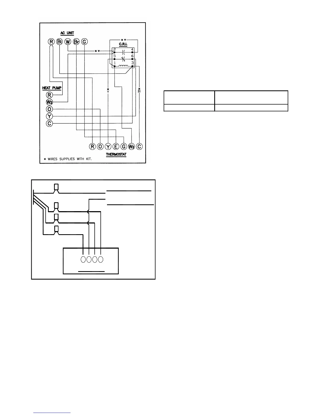
Figure 4
THERMOSTAT
R Y G W
BLUE
YELLOW
TO CONDENSING UNIT
24 V CONNECTIONS
Figure 5
Electrical Installation Diagram For Cooling
Electrical Installation Diagram For Heat pump
unit with Electric Heat.
With Electric Heat.
NOTE: In case of heat pump failure, switch to
“E” on T’stat for emergency heat.
3. Internal Wiring
A diagram of the internal wiring of this unit is located
under the electrical box cover. If any of the original wire
as supplied with the appliance must be replaced, the
wire gauge and insulation must be same as original
wiring.
4. Transformer is factory wired for 230 volts on 208/ 230 volt
models. See wiring diagram for 208 volt wiring. For 208V
operation, move the white transformer lead from 240V to
208V tap.
THERMOSTAT HEAT
ANTICIPATOR SETTING
AC18, 24, 30, 36 2
MODEL
MAINTENANCE
1) Room Thermostat - This is the device that controls the
operation of your heating and/or cooling unit. It senses
the indoor temperature and signals the equipment to
start or stop maintaining the temperature you have
selected for your comfort. The room thermostat should
be in a central, draft free inside wall location for best
operation. Do not place any heat producing apparatus
such as lights, radio, etc., near the thermostat as this
will cause erratic operation of the comfort system.
2) Air Filter(s) - All central air moving comfort systems
must include air filter(s). These filters will be located
either in the equipment or in the return air duct system
upstream of the equipment. The filter(s) removes dust
and debris from the air thus helping to keep your
conditioned space clean. More important, the filter
keeps dust and debris from collecting on heat transfer
surfaces thus maintaining optimum equipment effi-
ciency and performance. Inspect and clean or replace
filters every month. This routine maintenance procedure
will pay big dividends in reduced operating cost and
reduced service expense. Never operate comfort equip-
ment without filter(s).
3) Fuses and/or Circuit breakers - This comfort equip-
ment should be connected to the building electric
service in accordance with local and National Electric
codes. This electrical connection will include over
current protection in the form of fuses or circuit break-
ers. Have your contractor identify the circuits and the
location of over current protection so that you may be in
a position to make inspections or replacements in the
event the equipment fails to operate. Keep replacement
fuses of the proper size on hand.