SERVICING
36
ī±ī²ī·īØī Use adapter kit #0151K00000S to measure gas
pressure on White-Rodgers 36J22 gas valves.
ļ±ļ°.ļ°
ī°īīīīīīīīīī¬īīīīīīŖīīīī³īīīīīīī
īī¤īīīīīīīīīī°īīīīīī
3. Turn ON the gas and electrical power supply and op-
erate the furnace and all other gas consuming appli-
ances on the same gas supply line.
4. Measure furnace gas supply pressure with burners
īæīīīīīīī¶īīīīīīīīīīīīīīīīīīīīī
īīīīīīīīīīīīīīīīīīīīīīī-
īīæīīīīīīīīīīīīīīīīīīīīīīī
īīīī
Natural Gas Minimum: 4.5" w.c. ī°īīīīīīīīīīīīī
īīīīī
Propane Gas Minimum: 11.0" w.c. ī°īīīīīīīīīīīīī
īīīīī
ī¬ī±īÆīØī·īīŖī¤ī¶īī¶īøī³ī³īÆī¼īī³īµīØī¶ī¶īøīµīØ
ī¬īīīīīīīīīīīīīīīīīīīīó°Øīīīīīīīīīīī
īīīīīīīīīīīīīīīīīīīīīī-
justments to pressure regulator, gas piping size, etc., and/or
consult with local gas utility.
īŗī¤īµī±ī¬ī±īŖ
ī«ī¬īŖī«īī¹ī²īÆī·ī¤īŖīØ
ī§ļļļļļļļļļīī¤īÆīÆīļļļļļļļļļļīļļļļļīļļļīļļļļīļļļī
ļļļīļļļļļļ”īļļļļļļīļļļļļļļļļīļļīļļļļļļļļļļīļļļļī
ļļļļīīī°ļļļļļļļīļļļļļīļļļļļļļīļļļ”īļļīļļļļļļļīī
ī©ļļļļļļīļļīļļīļļīļļļ”īļļļļļīļļļļļļļļ”īļļļļļļīī
ļļļļļļļļīļļļļļļ”īļļīļļļļļī
5. ī§īīīīīīīīīīīīīīīīīīīīīīīīīīīīīīīīīīīó°Øīīīīīīīīīīīīīīī
īīīīīó°Øīīīīīīīīīµīīīīīīīīīīīīīīī
īīīīīīīīīīīīīīīīīīīīīīīī
furnace.
6. Turn OFF any unnecessary gas appliances started in
step 3.
7. Turn on gas to furnace and check for leaks. If leaks
are found, repair and then reinstall burner compart-
ment door.
8. Turn on electrical power and verify proper unit operation.
ī¤
īīīīīŖī¤ī¶
ī¶ī·īµīØī¤ī°
ī„
ī·īīīīīīīīīīīīī ī§īīīīīīīīīī³ī¤ī“īīīīīīīīīīīī īīīīīīīīīīīīī īŖīīī
ī¶īīīīīīī³ī„ī“ī
ī§īØī±ī·īī²īµ
ī„īøīµīµ
īŖī¤ī¶
ī¶ī·īµīØī¤ī°
ī„
ī¤ī īīīīī īīī ī
īīīī īīīīī īīīīīī īī īīīīīīī īīīīīīīīīī īīī īīīī īīīī
stream.
ī¦ī«īØī¦ī®ī¬ī±īŖīīŖī¤ī¶īī³īµīØī¶ī¶īøīµīØ
īŖļļīī¶ļļļļļ”īī³ļļļļļļļīī°ļļļļļļļļļļī
ī¦ī¤īøī·ī¬ī²ī±
ī·ļīļļļļļļļīļļļļļļļļļļīļļļļļļļļļīļļīļļļļļļļļļīļļļļļļīīļļļīļļļļļī
ļļļīļļļļļļ”īļļļļļļļļīļļļļīļļīļļīļļļļļļļļļīļļīļļļīļļļļīļļļļļļī
ļļļļļīļļļļīļļļīļļļļļīļļļļļļļļļīļļļīļļļļļīļļļļļļļļļīļļļļļļļļļī
Gas inlet and manifold pressures should be checked and
adjusted in accordance to the type of fuel being consumed.
The line pressure supplied to the gas valve must be within
īīīīīīīīīīīīīīīīæīīīī
īīīīīīī·īīīīīīīīīīīīīīīīīīīīīīīī
īīīīī-
īīīīīīīīīīīīīīīīīīīīīīīīīīīīīīīīīīīīīīīīīīīīīīīīīīīīīīīīæīīīīīī
installed in the gas piping drip leg. The supply pressure must
be measured with the burners operating. To measure the
gas supply pressure, use the following procedure.
īŗī¤īµī±ī¬ī±īŖ
ī§ļļļļļļļļļīļļļļļļļļļļīļļļļļīļļļīļļļļīļļļīļļļīļļļļļļ”ī
1. ī¤īīīīīīīīīīīīīīó°Øīīīīīīīīīīīīīīīīīīīīīīīīīīīīīīīīīīīīīī-
īó°Øīīīīīīīīīīīīīīīīīīīīīīīīīīīīīīīīīīīīīīīī
īīīīīīīīī-
partment door to gain access to the gas valve.
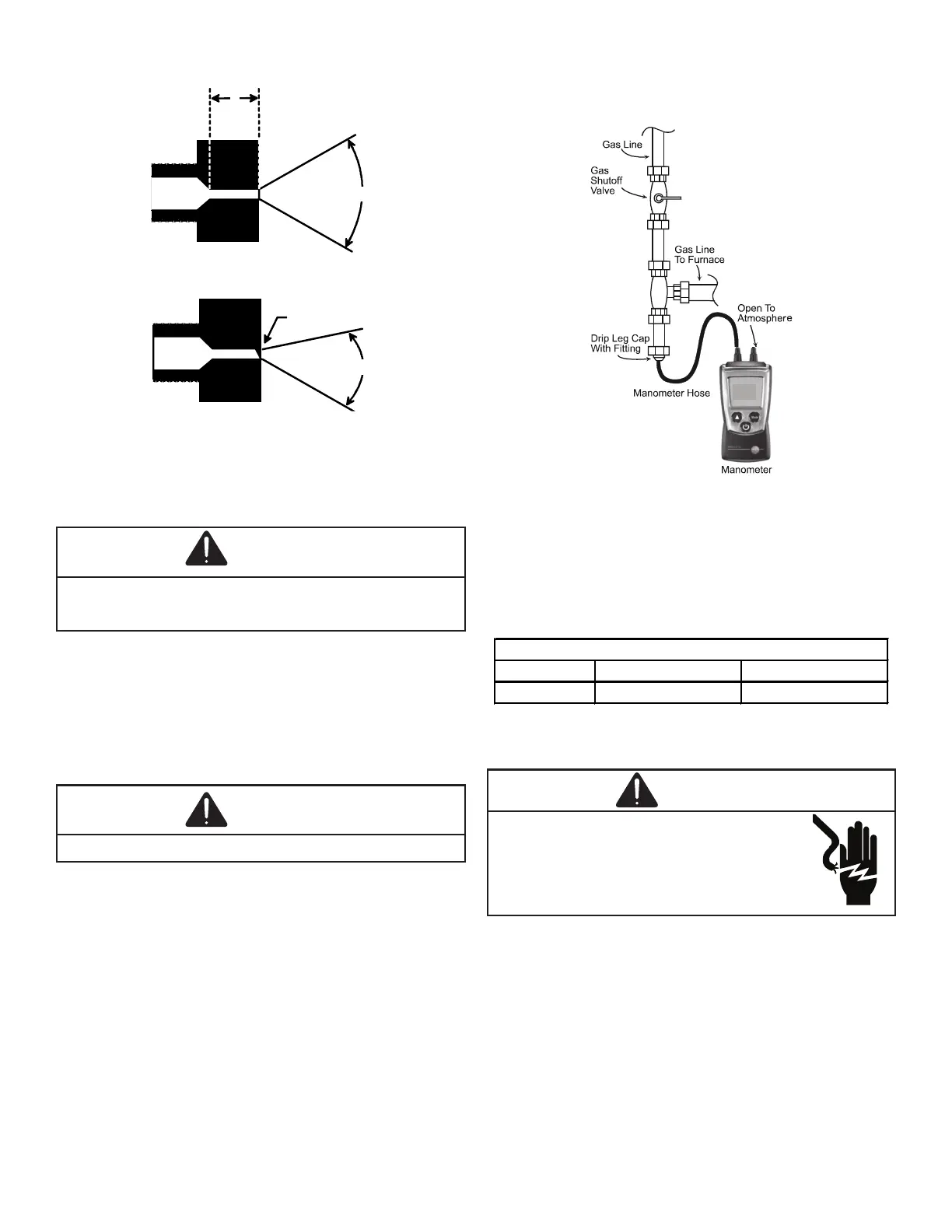
2. Connect a calibrated manometer (or appropriate gas
pressure gauge) at either the gas valve inlet pressure
tap or the gas piping drip leg as shown in the follow-
īīīīīæīīīīīīīīµīīīīīīīīMeasuring Gas Pressure: Single
Stage Valvesīīæīīīīīīīīīīīīīīīīīīīīīīīīīīīīīīīīīīīīīī-
sure tap connections.
ī±ī²ī·īØīī ī¤īī īīīīīīī īīīīīīīīīī īī īīīīī īæīīīīīī īīīīī ī
īī īīīīīīīīīī
prior to making the hose connection.