SERVICING
40
These tests must be completed within a given time frame
due to the operation of the ignition control.
The models use
1. Check for 120 volts from Line 1 (Hot) to Line 2 (Neu-
tral) at the ignition control. No voltage, check the door
switch connections and wire harness for continuity.
2. Check for 24 volts from W to C terminal on the ignition
control. No voltage. Check transformer, room thermo-
stat, and wiring.
between (C) and (R), check for blown fuse.
3. Check for 120 volts to the induced draft blower by
measuring voltage between Pin 1 (on the 2-pin con-
nector) and Line (Neutral) on the control board. No
voltage, replace ignition control.
4. If voltage is present in Steps 1 through 3 and the in-
duced draft blower is operating, check for 120 volts to
the ignitor during the preheat cycle. Measure voltage
between Pin 2 (on the 2-pin connector) and Line (Neu-
tral) on the control board. No voltage, check pressure
switch.
5. After the ignitor warmup time, begin checking for 24
volts to the gas valve. Voltage will be present for seven
-
not present the control will de-energize the gas valve and
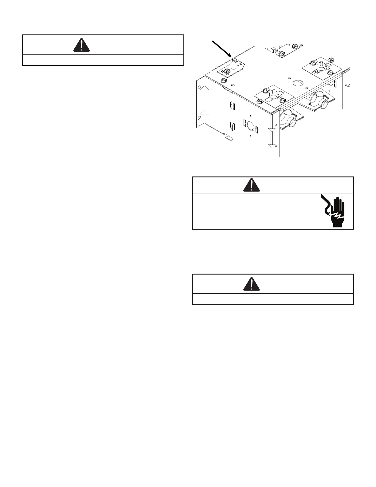
The following drawings illustrate from a bottom view, the ap-
gas in shot burner. You will note they are in the main burner
stream, not in the carry over ports as shown in the following
-
-
1.
sensor.
2. Connect a micro-amp meter in series with this wire
and the sensor terminal.
3. Place the unit into a heating cycle.
4. -
reading) is established, the hot surface ignitor will be
de-energized.
5. The Integrated Ignition controls will have 1 to 4 mi-
cro-amps. If the micro-amp reading is less than the
or poor grounding.
6. If absolutely no reading, check for continuity on all
components and if good - replace ignition control
module.
Contaminated fuel or combustion air can create a
-
with steel wool.