5
6.3 Downflow/Horizontal Right Installation
IMPORTANT NOTE: In the downflow application, to pre-
vent coil pan “sweating”, a downflow kit (DFK) is available
through your local distributor. The DFK is not supplied with
the air handler and is required by the manufacturer on all
downflow installations. See Table 1 for the correct DFK and
follow the instructions provided for installation.
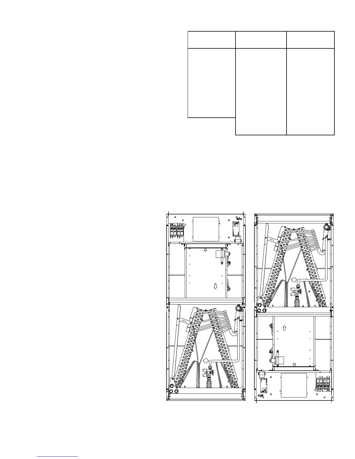
Refer to Figure 6 and 7 for the location of the components
referenced in the following steps.
1. Before inverting the air handler, remove blower access
panel and coil access panel. The coil access panel and
tubing panel may remain screwed together during this pro-
cedure. Remove and retain the seven (7) screws securing
the coil access panel to the cabinet and the six (6) screws
securing the blower access panel to the cabinet.
2. Slide the coil assembly out using the drain pan to pull the
assembly from the cabinet.
NOTE: DO NOT USE MANIFOLDS OR FLOWRATOR
TO PULL THE COIL ASSEMBLY OUT. FAILURE TO DO SO MAY RESULT IN BRAZE JOINT DAMAGE AND
LEAKS.
3. Removal of the center support is required on units with 21" wide cabinet. Remove and retain the two (2) screws that
secure the center support to the cabinet. Remove the center support.
4. Using the drain pan to hold the coil assembly, slide
the coil assembly back into the cabinet on the
downflow brackets as shown in Figure 8.
5. Re-install the center support (if removed) using
the two (2) screws removed in Step 4.
6. Re-install the access panels removed in Step 1
as shown in Figure 9.
7. The bottom left drain connection is the primary
drain for this application and condensate drain line
must be attached to this drain connection. The
top connection of the three drain connections on
the drain pan must remain plugged for this appli-
cation. The bottom left drain connection is for the
secondary drain line (if used).
DFK-B
Downflow Kit
DFK-C
Downflow Kit
DFK-D
Downflow Kit
ARUF18B14** ARUF30C14** ARUF48D14**
ARUF24B14** ARUF36C14** ARUF60D14**
ARUF30B14** ARUF42C14** ARPT36D14**
ARPT18B14** ARPT36C14** ARPT42D14**
ARPT24B14** ASPT30C14** ARPT48D14**
ARPT30B14** ASPT36C14** ARPT60D14**
ASPT24B14** ASPT42C14** ASUF59D14**
ASUF29B14** ASPT48C14** ASPT42D14**
ASUF39C14** ASPT48D14**
ASUF49C14** ASPT60D14**
MODEL LIST FOR DOWNFLOW KITS
DOWNFLOW KIT
Table 1
UPFLOW DOWNFLOW
Figure 2 Figure 3