8
7.3 Special Instructions
Units without a factory installed TXV come equipped with a flowrator piston for refrigerant expansion. For most instal-
lations with matching applications, no change to the flowrator piston is required. However, in mix-matched applica-
tions, a flowrator piston change may be required. See the piston kit chart (provided in the literature packet) or consult
your local distributor for details regarding mix-matched flowrator piston sizing. If the mix-match application requires a
different flowrator piston size, change the flowrator piston in the flowrator body on the indoor coil before installing the
coil and use the procedure in section 8.4.
NOTE: The use of a heat shield is strongly recommended when brazing to avoid burning the serial plate or the finish
of the unit. Heat trap or wet rags must be used to protect heat sensitive components such as service valves and TXV
valves sensing bulb.
7.4 Tubing Connections for Flowrator Model
1. Loosen the 13/16 nut 1 TURN ONLY to allow high pressure tracer
gas to escape. No gas indicates a possible leak.
2. After the gas has been expelled, remove the nut and discard the
black or brass cap plastic seal.
3. Remove the flowrator piston to verify it is the correct size for the
outdoor unit being installed and then replace the piston (changing
size, if needed). See piston kit chart in the literature kit for appropri-
ate piston size.
4. Remove the spin closure on the suction line using a tube cutter and
deburr the tube.
5. Insert the suction line into the connection, slide the insulation and
the rubber grommet at least 18" away from the braze joint.
6. Remove the tailpiece clamped to the exterior of the cabinet or in
the literature kit packet and slide the 13/16 nut into place.
7. Braze tailpiece to the line set liquid tube and braze suction line
connection. Quench all brazed joints with a damp rag upon comple-
tion of brazing. Do not allow water to enter the inside of the tubing.
8. AFTER THE TAILPIECE HAS COOLED, confirm position of the
white Teflon
®
seal and hand tighten the 13/16 nut.
9. Torque the 13/16 nut to 7-25 ft-lbs. or tighten 1/6 turn.
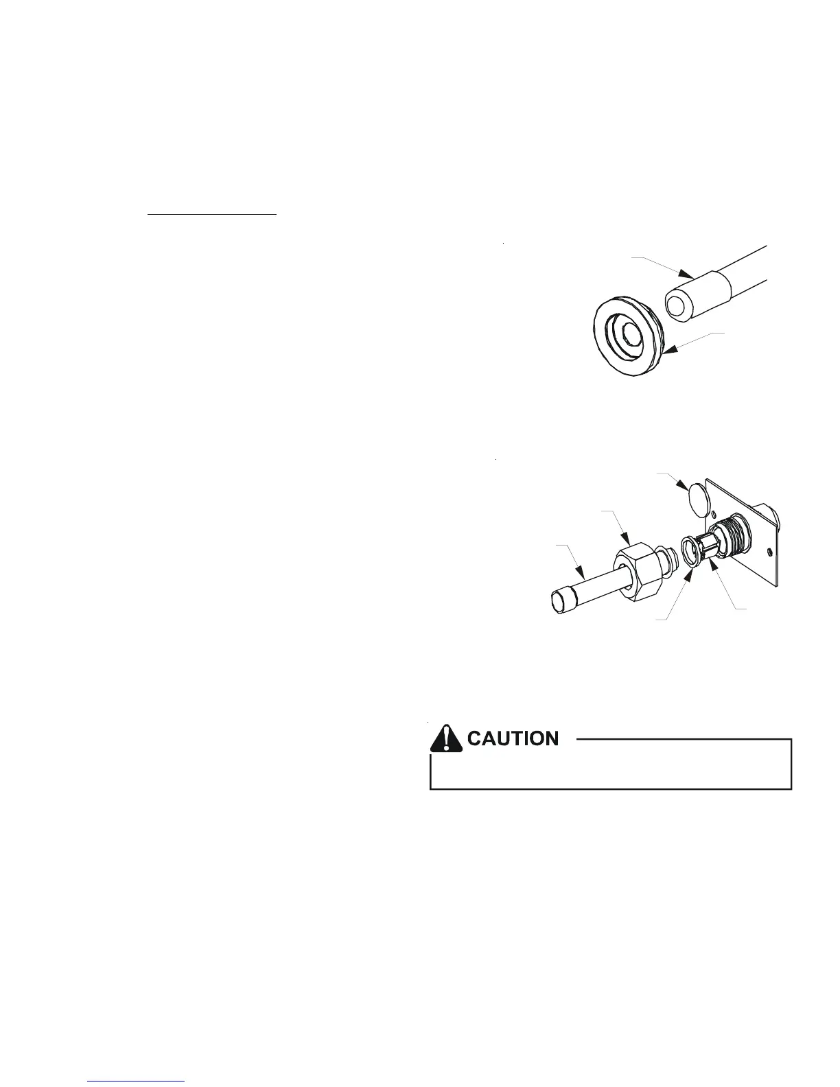
RUBBER
GROMMET
SUCTION LINE
WITH SPIN CLOSURE
SUCTION SPUN END AND GROMMET
Figure 10
WHITE
TEFLON SEAL
PISTON
TAILPIECE
13/16” NUT
PLASTIC or BRASS CAP
TAILPIECE JOINT
Figure 11
Excessive torque can cause orifices to stick. Use the
proper torque settings when tightening orifices.
7.5 Tubing Connections for TXV Models
TXV models come with factory installed TXV with the bulb pre-installed on the vapor tube.
1. Remove refrigerant tubing panel or coil (lower) access panel.
2. Remove access valve fitting cap and depress the valve stem in access fitting to release pressure. No pressure indi-
cates possible leak.
3. Replace the refrigerant tubing panel.
4. Remove the spin closure on both the liquid and suction tubes using a tubing cutter.
5. Insert liquid line set into liquid tube expansion and slide grommet about 18" away from braze joint.
6. Insert suction line set into suction tube expansion and slide insulation and grommet about 18" away from braze joint.
7. Braze joints. Quench all brazed joints with water or a wet rag upon completion of brazing.