EasyManua.ls Logo

Goodman GPH1330M41 User Manual

Goodman GPH1330M41
16 pages
To Next Page IconTo Next Page
Page #1 background imageLoading...
Page #1 background image
C
US
®
*NOTE: Please contact your distributor or our
website for the applicable Specification Sheets
referred to in this manual.
RECOGNIZE THIS SYMBOL AS A SAFETY PRECAUTION.
ATTENTION INSTALLING PERSONNEL
Prior to installation, thoroughly familiarize yourself with this Installation Manual. Observe all safety warnings. During
installation or repair, caution is to be observed.
It is your responsibility to install the product safely and to educate the customer on its safe use.
These installation instructions cover the outdoor
installation of self contained package air conditioners
and heating units. See the Specification Sheets
applicable to your model for information regarding
accessories.
Goodman Manufacturing Company, L.P.
5151 San Felipe, Suite 500, Houston, TX 77056
www.goodmanmfg.com www.amana-hac.com
© 2010-2011 Goodman Manufacturing Company, L.P.
I
NSTALLATION
I
NSTRUCTIONS
F
OR
S
ELF
-C
ONTAINED
P
ACKAGE
A
IR
C
ONDITIONERS
AND
H
EAT
P
UMP
U
NITS
GPC/GPH 13 SEER “M” SERIES
W
ITH
R-410A
IO-395B
9/2011
is a registered trademark of Maytag Corporation or its related companies and is used under
license to Goodman Company, L.P., Houston, TX. All rights reserved.
Question and Answer IconNeed help?

Do you have a question about the Goodman GPH1330M41 and is the answer not in the manual?

Goodman GPH1330M41 Specifications

General IconGeneral
TypePackaged Heat Pump
SEER Rating13
Voltage208/230 V
Phase1
RefrigerantR-410A
Compressor TypeScroll
Cooling Capacity30000 BTU/h
Unit Weight260 lbs
Tonnage2.5

Summary

ATTENTION INSTALLING PERSONNEL

GENERAL SAFETY PRECAUTIONS

Emphasizes familiarization with manual, observing safety warnings, and caution during installation or repair.

TO THE INSTALLER

SAFETY INSTRUCTIONS

MANDATORY SAFETY WARNINGS

Highlights crucial safety warnings, including using only approved devices, high voltage hazards, and fire/explosion risks.

PRE-INSTALLATION CHECKS

ROOF TOP PRE-INSTALLATION DETAILS

RIGGING DETAILS

WIRING

HIGH VOLTAGE WIRING

Details connections for single and three-phase high voltage wiring, emphasizing wire sizing and conduit.

LOW VOLTAGE WIRING

Outlines 24V thermostat wiring connections for both air conditioners and heat pumps, including wire gauge.

STARTUP, ADJUSTMENTS, AND CHECKS

START-UP PROCEDURE AND CHECKLIST

Step-by-step guide for initial unit startup in cooling mode, including thermostat settings and blower operation checks.

HEAT PUMP START-UP PROCEDURE

Detailed steps for starting up the heat pump in cooling and heating modes, including reversing valve operation and defrost cycle checks.

FINAL SYSTEM CHECKS

Verifies proper air distribution, ductwork integrity, unit vibration, and instructs on thermostat settings for normal use.

HEAT PUMP OPERATION

SUGGESTED FIELD TESTING/TROUBLE SHOOTING

AIRFLOW MEASUREMENT AND ADJUSTMENT

Guides on measuring external static pressure, CFM, and adjusting blower speed for optimal airflow.

SPEED TAP ADJUSTMENTS FOR INDOOR BLOWER MOTOR

REFRIGERANT CHARGE CHECKS

MAINTENANCE

COMMON HEAT PUMP HEATING ISSUES

Identifies common problems like inadequate indoor airflow, outside air introduction, undercharge, and reversing valve malfunctions.
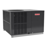
TROUBLESHOOTING CHART

Related product manuals