EasyManua.ls Logo

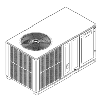
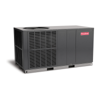
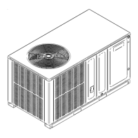
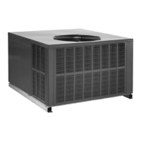
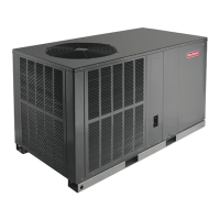
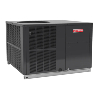
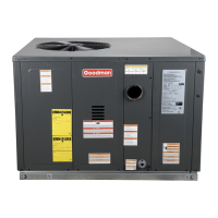
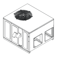
Goodman GPC SERIES User Manual

Goodman GPC SERIES
12 pages
To Next Page IconTo Next Page
Page #1 background imageLoading...
Page #1 background image
Goodman Manufacturing Company, L.P.
IO-313 2550 North Loop West, Suite 400, Houston, TX 77092 06/06
www.goodmanmfg.com www.amana-hac.com
© 2005-2006 Goodman Manufacturing Company, L.P.
All information contained herein is subject to change without notice.
INSTALLATION & OPERATING
INSTRUCTIONS FOR
SELF CONTAINED PACKAGE
AIR CONDITIONERS AND
HEAT PUMPS
GPC/GPH SERIES

Questions and Answers:

Goodman GPC SERIES Specifications

General IconGeneral
RefrigerantR-410A
StagesSingle
SEER RatingUp to 16 SEER
Cooling Capacity (BTU/h)18, 000 - 60, 000 BTU/h
Compressor TypeSingle-Stage
Warranty10-year limited parts warranty

Summary

Installation & Operating Instructions for Self-Contained Package Air Conditioners and Heat Pumps GPC/GPH Series

Important Safety Instructions

Recognize Safety Symbols, Words, and Labels

Understand hazard symbols, words, and labels for safety compliance and risk reduction.

Installation

Pre-Installation Checkpoints

Essential pre-installation considerations including structural integrity, clearances, power, and duct connections.

Ducting

Connecting the Return and Supply Flexible Duct

Guidelines for attaching flexible ductwork using converter kits and proper sealing.

Plenum Application

Requirements for plenum construction and insulation for exposed ductwork.

Filters

Filters are not included; installer must supply and install with adequate face area.

Piping

Condensate Drain

Proper installation of a condensate drain trap with a positive liquid seal is required.

Wiring

High Voltage Wiring

Instructions for connecting high voltage power supply to unit terminals.

Low Voltage Wiring

Wiring 24V control wires from thermostat to unit control box for AC and Heat Pumps.

Operation

Start-Up Procedure and Checklist

Step-by-step guide for initial unit startup and operational checks.

Heat Pump Start-Up Procedure

Specific procedures for starting up heat pump in cooling and heating modes.

Final System Checks

Final checks on air distribution, ductwork, unit rattles, and owner instruction.

Components

Contactor

Control activated by thermostat to supply power to compressor and outdoor fan motor.

Crankcase Heater

Heater activated when power is supplied to prevent liquid migration and compressor damage.

Condenser Motor

Activated by contactor during heating/cooling, except during defrost and emergency heat.

Explanation and Guidance (Heat Pump)

Heat Pump Refrigerant Circuit

Schematic illustrating refrigerant flow for cooling and heating cycles.

Defrost Control

Suggested Field Testing/Trouble Shooting

Air Flow Measurement and Adjustment

Procedures for measuring and adjusting airflow using blower curves and ESP.

Adjusting Speed Tap for Indoor Blower Motor

PSC Motor

Adjusting CFM by changing speed taps on EBTDR 'com' connection.

X-13 Motor

Setting blower speed for cooling, heat pump, and electric heat using 24V leads.

Checking Charge

Superheat Can Be Determined As Follows

Method for determining superheat using suction pressure and temperature readings.

Electric Heat Installation & Adjustment

Troubleshooting Chart

Related product manuals