
S
Sandra EnglishSep 23, 2025
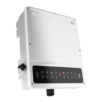
What does SPI failure mean on a Goodwe GW5048-ESA?
- JJessica WebbSep 23, 2025
SPI failure on your Goodwe Inverter indicates an internal communication failure.
What does SPI failure mean on a Goodwe GW5048-ESA?
SPI failure on your Goodwe Inverter indicates an internal communication failure.
What does FAC failure mean on a Goodwe GW5048-ESA Inverter?
FAC failure on your Goodwe Inverter indicates that the grid frequency is no longer within the permissible range.
What causes Over temperature on Goodwe GW5048-ESA?
Over temperature on your Goodwe Inverter means there is over temperature on the case.
What does Isolation failure mean for a Goodwe GW5048-ESA?
Isolation failure on your Goodwe Inverter indicates that the ground insulation impedance is too low.
What does Ground l failure mean on a Goodwe GW5048-ESA Inverter?
Ground l failure on your Goodwe Inverter indicates excessive ground leakage current.
What does GFCl failure mean on a Goodwe GW5048-ESA?
GFCl failure on your Goodwe Inverter indicates a detection circuit of ground leakage current failure.
What does DC injection failure mean for a Goodwe GW5048-ESA Inverter?
DC injection failure on your Goodwe Inverter means there is excessive DC current in AC output.
What does AC HCT failure mean on a Goodwe Inverter?
AC HCT failure on your Goodwe Inverter indicates an output current sensor failure.
What does Battery cell voltage differences mean on a Goodwe GW5048-ESA Inverter?
Battery cell voltage differences on your Goodwe Inverter indicates Li-ion battery cell voltage differences.
What does Battery communication failure mean on a Goodwe GW5048-ESA?
Battery communication failure on your Goodwe Inverter means the battery communication has failed.
Lists the various capabilities and operational aspects of the hybrid inverter.
Highlights key technical and physical features of the inverter, like protection and enclosure.
Provides guidance and requirements for selecting compatible battery types and banks.
Details the physical size and required installation clearances for the inverter unit.
Explains how to connect and manage AC loads for backup power supply.
Details the default operational mode prioritizing PV, then battery, then grid.
Explains the setup for a pure off-grid system using photovoltaic and battery.
Describes the mode where the battery acts as a backup during grid outages.
Covers the mode for optimizing charging/discharging based on electricity prices.
Lists all components supplied with the GoodWe GW5048-ESA inverter.
Specifies suitable locations and environmental conditions for inverter installation.
Lists the recommended tools for safely installing the inverter system.
Instructions for installing the battery enclosure prior to inverter setup.
Details the process of mounting the wall plate for the inverter.
Guidance on securely mounting the Balance of System components.
Step-by-step instructions for physically attaching the inverter to the mounting plate.
Procedure for accessing internal compartments by removing specific covers.
General guidelines and considerations for wiring the BoS components.
Visual representation of the complete system wiring connections.
Instructions and requirements for proper grounding (PE) connections.
Details on connecting the solar array to the inverter, including safety.
Procedures for correctly wiring the battery bank to the inverter.
How to establish communication between the Battery Management System (BMS) and the inverter.
Guidelines for AC wiring connections and the selection of circuit breakers.
Instructions for connecting the inverter to the main AC utility grid.
How to connect the inverter to the backup AC loads panel.
Steps for connecting the utility grid energy meter for monitoring.
Explains the function and positions of the circuit breakers and bypass switch.
Step-by-step guide for powering up and starting the inverter system.
Step-by-step guide for safely powering down the inverter system.
Description of LED indicators and their meanings for system status.
Detailed steps for configuring the inverter's Wi-Fi connection.
Information on the PV Master app for monitoring and configuration.
Details on the CEI auto-test function integrated into the PV Master app.
A comprehensive list of error messages and their corresponding descriptions.
Technical data related to the battery enclosure, including weight and dimensions.
Detailed parameters for battery input, PV string input, and AC output.
Information on system efficiency ratings and integrated protection features.
Covers operating temperature, humidity, dimensions, and other general data.
Lists the certifications and standards the inverter complies with.
| Model | GW5048-ESA |
|---|---|
| Rated Power | 5000 W |
| Max. DC Input Power | 6000 W |
| Start Voltage | 120 V |
| Number of MPP Trackers | 2 |
| Rated AC Output Power | 5000 W |
| Max. AC Apparent Power | 5000 VA |
| Rated AC Voltage | 230 V |
| AC Voltage Range | 180-280 V |
| Total Harmonic Distortion (THDi) | < 3% |
| AC Grid Connection Type | Single Phase |
| Switching Time | < 10 ms |
| Battery Voltage Range | 40-60 V |
| Max. Charging Current | 100 A |
| Max. Discharging Current | 100 A |
| Protection Degree | IP65 |
| Efficiency | 97.6% |
| Input Voltage Range | 90 V - 450 V |
| Rated Grid Frequency | 50 Hz |
| DC Injection Current | <0.5% In |
| Communication | RS485 / WiFi / Ethernet |
| Operating Temperature Range | -25 ~ +60 °C |
| Battery Type | Lithium-ion |