Operation
6.
7.
Take note of how the cable enters the board and then
remove it
by
using the pull-tab. This cable
is
the con-
nector to the GPIB interface.
Remove the
1/0
board taking care not to damage the
GPIB cable on the rear
of
the board.
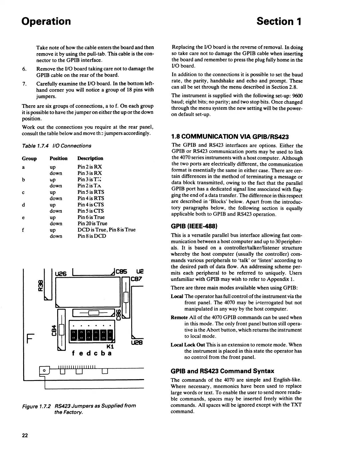
Carefully examine the
1/0
board. In the bottom left-
hand comer you will notice a group
of
18
pins with
jumpers.
There are six groups
of
connections, a to
f.
On
each group
it
is
possible to have the jumper on either the up
or
the down
position.
Work out the connections you require at the rear panel,
consult the table below and move
th:
jumpers accordingly.
Table
1.7.4
110
Connections
Group
Position
Description
a
up
Pin2isRX
down
Pin3isRX
b up
Pin3isl,~
down
Pin2isTA
c
up
Pin5isRTS
down
Pin4isRTS
d
up
Pin4isCTS
down
Pin5isCTS
e up
Pin6isTrue
down Pin 20
is
True
f
up
DCD
is True, Pin 8 is True
down
Pin8isDCD
~Uj
_dces
UC
I
C87
~
--c:J-
Ji
~
u
~
. . . . .
F
U28
Kl
fedcba
Figure 1.7.2 RS423 Jumpers as Supplied from
the Factory.
22
Section 1
Replacing the
1/0
board
is
the reverse
of
removal. In doing
so take care not to damage the
GPIB cable when inserting
the board and remember to press the plug fully home in the
1/0
board.
In addition to the connections it
is
possible to set the baud
rate, the parity, handshake and echo and prompt. These
can all be set through the menu described
in
Section 2.8.
The instrument
is
supplied with the following set-up: 9600
baud; eight bits; no parity; and two stop bits. Once changed
through the menu system the new setting will be the power-
on default set-up.
1.8
COMMUNICATION
VIA
GPIB/RS423
The GPIB and
RS423
interfaces are options. Either the
GPIB
or
RS423 communication ports may be used to link
the
4070 series instruments with a host computer. Although
the two ports are electrically different, the communication
format
is
essentially the same
in
either case. There are cer-
tain differences
in
the method
of
terminating a message
or
data block transmitted, owing to the fact that the parallel
GPIB port has a dedicated signal line associated with flag-
ging the end of a data transfer. The difference
in
this respect
are described
in
'Blocks' below. Apart from the introduc-
tory paragraphs below, the following section
is
equally
applicable both to GPIB and RS423 operation.
GPIB (IEEE-488)
This
is
a versatile parallel bus interface allowing fast com-
munication between a host computer and up to
30
peripher-
als.
It
is
based on a controller/talker/listener structure
whereby the host computer (usually the controller) com-
mands various peripherals to 'talk'
or
'listen' according to
the desired path of data flow. An addressing scheme per-
mits each peripheral to be referred
to
uniquely. Users
unfamiliar with GPIB may wish to refer to Appendix
1.
There are three main modes available when using GPIB:
Local The operator has full control
of
the instrument via the
front panel. The
4070 may be il'terrogated but not
manipulated
in
any way by the host computer.
Remote All
of
the
4070
GPIB commands can be used when
in
this mode. The only front panel button still opera-
tive
is
the Abort button, which returns the instrument
to local mode.
Local Lock Out This
is
an extension to remote mode. When
the instrument
is
placed in this state the operator has
no control from the front panel.
GPIB and RS423 Command Syntax
The commands of the
4070
are simple and English-like.
Where necessary, mnemonics have been used to replace
large words
or
text. To enable the user to send more reada-
ble commands, spaces may be inserted freely within the
commands. All spaces
will
be ignored except with the TXT
command.
 Loading...