Introduction
NOTE:
This
is
a combim:d <>perating manual for the
-W71
and 4072 2-Channel and the 4074 4-Channel Digital Storage
Osei 1
loscopes.
Throughout
the operating manual the following convention
~tpplies:-
4070 - refers to the 4071. 4072 and 4074.
4071
- refers to only the 2 channel 4071.
4072 - refers to only the 2 channel 4072.
4074 -
refers to only the 4 channel 4074.
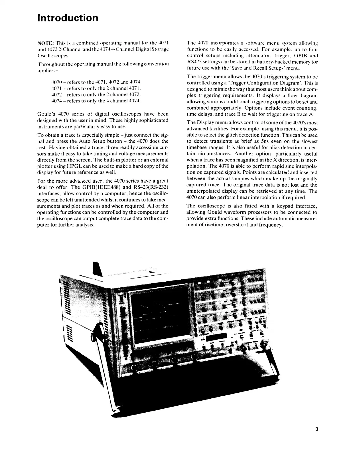
Gould's
4070 series
of
digital oscilloscopes have been
designed with the user
in
mind. These highly sophisticated
instruments are
particularly easy to use.
To
obtain
a trace
is
especially simple - just connect the sig-
nal and press the
Auto
Setup
button
- the 4070 does the
rest. Having
obtained
a trace, three readily accessible cur-
sors
make
it easy to take timing and voltage measurements
directly from the screen.
The
built-in
plotter
or
an external
plotter
using
HPGL
can be used to make a hard copy
of
the
display for future reference as well.
For the more
adv<wced user, the 4070 series have a great
deal to offer.
The
GPIB(IEEE488)
and RS423(RS-232)
interfaces. allow control by a computer, hence the oscillo-
scope can be left
unattended
whilst it continues to take mea-
surements
and
plot traces as
and
when required. All
of
the
operating
functions can be controlled by the
computer
and
the oscilloscope can
output
complete trace
data
to the com-
puter
for
further
analysis.
The 4070 incorporates a software menu
'ystem
allowing
functions to be easily accessed. For example. up to four
control
setups including
attenuator.
trigger.
GPIB
and
RS423 settings can be stored
in
battery-backed memory for
future
use with the 'Save and Recall St:tups' menu.
The
trigger menu allows the 4070's triggering system to be
controlled using a 'Trigger
Configuration Diagram·. This
is
designed to mimic the way that most users think about com-
plex triggering requirements.
It
displays a flow diagram
allowing various conditional triggering options to be set and
combined appropriately.
Options include event counting.
time delays. and trace B to wait for triggering on trace A.
The
Display menu allows control
of
some
of
the 4070's most
advanced facilities. For example, using this
menu,
it
is
pos-
sible to select the glitch detection function. This can be used
to detect transients as brief as 5ns even on the slowest
timebase ranges. It
is
also useful for alias detection
in
cer-
tain circumstances.
Another
option,
particularly useful
when a trace has been magnified in the X direction.
is
inter-
polation.
The
4070
is
able to perform rapid sine interpola-
tion
on
captured
signals. Points are
calculate~
and inserted
between the actual samples which make up the originally
captured
trace.
The
original trace
data
is
not lost and the
uninterpolated display can be retrieved
at
any time. The
4070 can also perform linear interpolation if required.
The
oscilloscope
is
also fitted with a keypad interface,
allowing
Gould
waveform processors
to
be
connected
to
provide
extra
functions. These include automatic measure-
ment
of
risetime, overshoot
and
frequency.
3
 Loading...