Operation
1.0 SAFETY AND POWER REQUIREMENTS
Safety Warning
(as required for
l.E.C.
348
Class I)
This instrument manual contains information and warnings
which must be observed by the user to ensure safe operation
and retain the apparatus in a safe condition. The instrument
has been designed for indoor use within the specified limits
of temperature, i.e.
0 to
50
deg. C.
It
should not be switched
on if there are obvious signs
of
mechanical damage and it
should not be used under wet conditions.
Grounding
The ir1strument must be operated with a protective ground
connected via the appropriate (yellow/green) conductor
of
the supply cable. This
is
connected to the instrument before
the line and neutral supply connections when the supply
plug
is
inserted into the socket on the back
of
the instru-
ment.
If
the final connection between this and the supply is
made elsewhere,the user must ensure the ground connec-
tio•.
is
made before line and neutral.
If
any supply cable other than that supplied with the instru-
ment
is
used, it must carry an adequate protective ground
conductor.
Any interruption
of
the protective ground conductor inside
or
outside the instrument
is
likely
to
make the instrument
dangerous. Intentional interruption
is
prohibited.
Signal connections into the instrument should be connected
after and disconnected before the protective ground con-
nection
is
made, i.e. the supply lead must be connected at
all times that signal leads are connected.
Live Parts
The instrument
is
safe to operate with covers fitted and
these must not be removed under normal usage. The covers
protect the user from live parts and they should
be
removed
only by suitably qualified personnel for maintenance and
repair purposes.
WARNING: Removing the covers
may
expose vol-
tages in excess
of
2000V,
in
particular
at
the rear
of
the
tube, even when the instrument has been discon-
nected from the
power
source
for
some time.
Ventilation and Dust
The instrument relies on fan assisted cooling and must not
be operated in a position which restricts air flow through the
air intake in the back
of
the instrument and the ventilation
slots in the sides. The instrument should not therefore be
used in a tightly fitting rack as this
will
limit ventilation.
4
Section 1
Adequate ventilation can usually be achieved
by
leaving an
8cm gap around the top, rear and sides
of
the instrument.
The instrument should not be operated
in
dusty environ-
ments.
Operating Temperatures
The instrument
is
designed to be operated in an environ-
ment having an ambient temperature
of
between 0 deg. C
and
50
deg. C. The instrument
is
only guaranteed to operate
with full accuracy within a temperature range
of
15
deg. C
to
35
deg.
C.
Note: The use
of
the instrument in strong direct sunlight or
next to radiators and other heat sources may
m<
••
kedly
increase the temperature
of
the instrument and this should
be taken into account when assessing the viability of using
the instrument in a given environment.
Power and Frequency Requirements
The instrument
is
designed
to
consume less than 200W and
operate from supply voltages
of
between 90V
aru
265V,
without any need for mains tap switching.
It
will
operate at supply frequencies
of
between 45Hz
minimum and
440Hz maximum.
Under the extreme conditions
of
90V and 45Hz, the instru-
ment
will
still operate properly even if there
is
a half cycle
dropout in the mains supply.
Fuse
Requirements
Despite the fact that the instrument operates at less than
200W, it draws a large current
on
power-up and so the fol-
lowing fuse arrangement must be followed:
* one
4A
HRC
fuse
on
the rear panel; (Gould part no.
457032)
* one 3.15A
HRC
fuse inside the instrument, under the
panel at the rear left side (Gould part no. 456327).
* for instruments in the
U.K.
one 13A fuse in the mains
supply plug;
Note:
The
HRC
(High Rupturing Capacity) fuses
must
not
be replaced
by
normal
fuses. Use
HRC
or
HBC
fuses
rated to break
at
1500A.
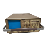
1.1
GEmNGSTARTED
This section of the manual
is
aimed at the first-time user of
the
4070 oscilloscope. It describes how to set up the instru-
ment and how to go about displaying a signal. Later sections
of
this manual
will
cover many
of
the features mentioned
here in greater detail and at a more advanced level.
 Loading...