Appendix 1
BRIEF
IEEE-488
BUS
DISCUSSION
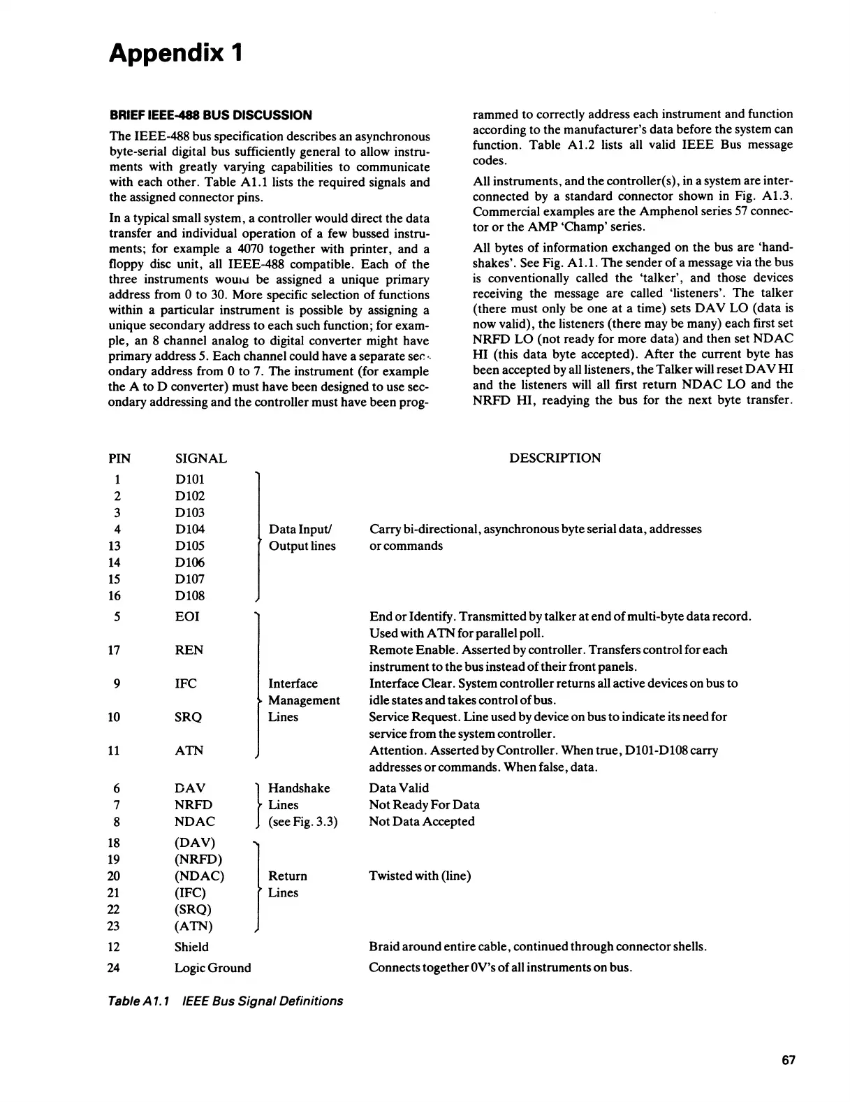
The
IEEE-488 bus specification describes an asynchronous
byte-serial digital bus sufficiently general
to
allow instru-
ments with greatly varying capabilities
to
communicate
with each
other.
Table
Al.I
lists the required signals
and
the
assigned
connector
pins.
In
a typical small system, a controller would direct
the
data
transfer
and
individual
operation
of
a few bussed instru-
ments; for example a
4070 together with printer, and a
floppy disc unit, all
IEEE-488
compatible.
Each
of
the
three
instruments
wouh.J
be
assigned a unique primary
address from
0
to
30.
More
specific selection
of
functions
within a particular instrument is possible by assigning a
unique secondary address
to
each such function; for exam-
ple, an 8 channel analog
to
digital converter might have
primary address 5.
Each
channel could have a
separate
sei:
··
ondary
address from 0
to
7.
The
instrument (for example
the
A
to
D converter) must have been designed
to
use sec-
ondary
addressing
and
the
controller must have
been
prog-
PIN
SIGNAL
1
DlOl
2 D102
3
D103
rammed
to
correctly address each instrument and function
according
to
the
manufacturer's
data
before
the
system can
function. Table
Al
.2 lists all valid
IEEE
Bus message
codes.
All instruments, and
the
controller( s), in a system are inter-
connected by a standard
oonnector shown in Fig.
Al.3.
Commercial examples
are
the
Amphenol
series 57 connec-
tor
or
the
AMP
'Champ'
series.
All bytes
of
information exchanged
on
the
bus
are
'hand-
shakes'. See Fig.
Al.1.
The
sender
of
a message via
the
bus
is conventionally called
the
'talker',
and those devices
receiving
the
message
are
called 'listeners'.
The
talker
(there must only
be
one
at
a time) sets
DAV
LO
(data
is
now valid),
the
listeners
(there
may
be
many) each first set
NRFD
LO
(not
ready for
more
data)
and
then
set
NDAC
HI
(this
data
byte accepted).
After
the
current byte has
been
accepted by all listeners,
the
Talker
will reset
DAV
HI
and
the
listeners will all first
return
NDAC
LO
and
the
NRFD
HI,
readying
the
bus for
the
next byte transfer.
DESCRIPTION
4
D104
Data
Input/
Carry
bi-directional, asynchronous byte serial
data,
addresses
13
D105
Output
lines
or
commands
14
D106
15
D107
16
Dl08
5
EOI
End
or
Identify. Transmitted by talker
at
end
of
multi-byte
data
record.
Used
with A
TN
for parallel poll.
17
REN
Remote
Enable.
Asserted
by controller. Transfers control for each
instrument
to
the
bus instead
of
their
front panels.
9
IFC
Interface
Interface
Oear.
System controller returns all active devices
on
bus
to
Management idle states
and
takes control
of
bus.
10
SRQ
Lines
Service
Request.
Line used by device
on
bus
to
indicate its
need
for
service from
the
system controller.
11
ATN
Attention.
Asserted by Controller.
When
true,
D101-D108 carry
addresses
or
commands.
When
false, data.
6
DAV
}
Handshake
Data
Valid
7
NRFD
Lines
Not
Ready
For
Data
8
NDAC
(see Fig. 3.3)
Not
Data
Accepted
18
(DAV)
19
(NRFD)
20
(NDAC)
Return
Twisted with (line)
21
(IFC)
Lines
22
(SRQ)
23
(ATN)
12 Shield
Braid
around
entire
cable, continued through connector shells.
24 Logic
Ground
Connects
together
OV's
of
all instruments
on
bus.
Table A
1.
1
IEEE
Bus Signal Definitions
67
 Loading...