Operation
PowerOn
G)
After
connecting
the
oscilloscope
to
the supply, press the
POWER
button situated in the top-left corner
of
the front
panel
of
the oscilloscope. A light should
appear
above the
button.
After
the automatic calibration procedure which
takes less than a minute, the display will
be
as shown in
Figure 1.1.1.
The
display may
need
some adjustment.
The
following rot-
ary controls can
be
used to adjust the display.
Trace Intensity @ This controls the brightness
of
the
'trace', i.e.
of
the
part
of
the display used
to
show any
signal.
At
the
moment,
the
trace will
be
visible as an
approximately horizontal line across the centre
of
th~
display.
The
brightness
of
the cursors and the trigger
level indicator
are
also adjusted by this control.
Alpha Intensity @ This is used to control the brightness
of
the characters displayed
on
the screen.
Focus © Controls the focus
of
the display.
Scale Illumination @
The
grid
on
the screen can
.1:-e
illuminated using this control.
Trace Rotate @
If
the
trace with input grounded
is
not
properly horizontal relative to the scale, then adjust-
ment
of
this control with a small screwdriver allows
this to
be
corrected.
trigger level
Indicator
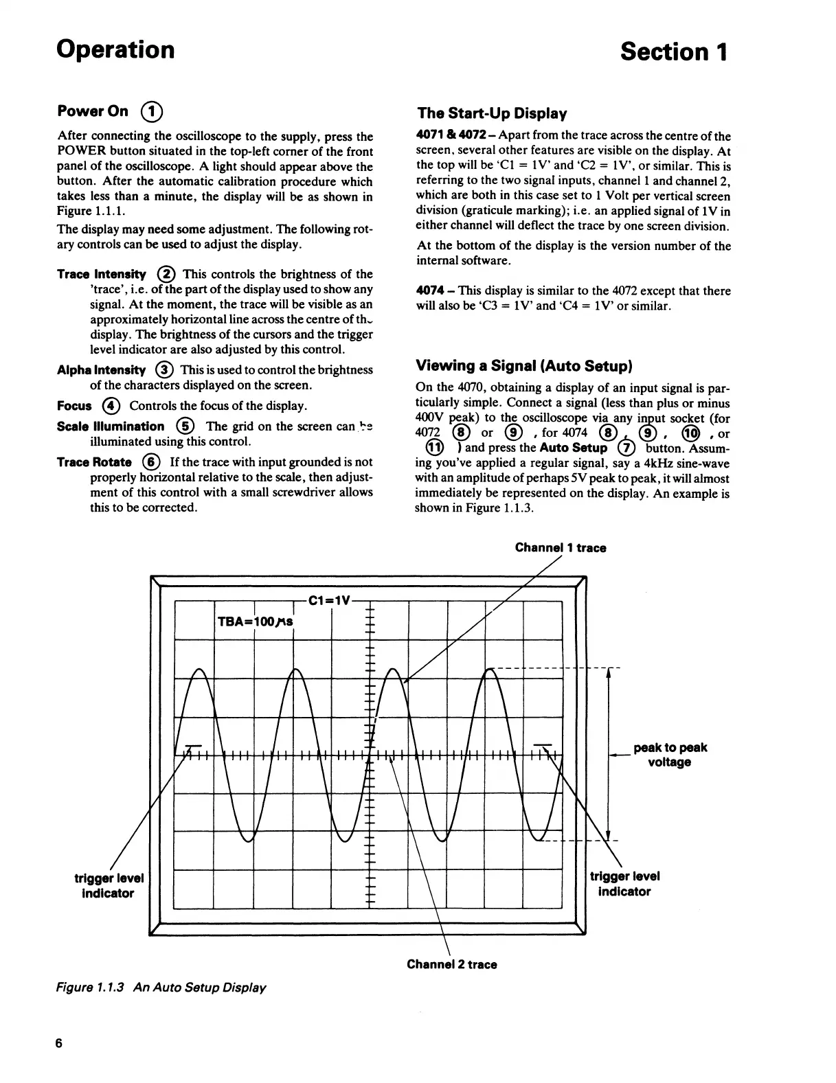
Figure 1.1.3
An
Auto
Setup Display
6
Section 1
The Start-Up Display
4071
lk
4072-
Apart
from the trace across the centre
of
the
screen, several
other
features are visible on the display.
At
the
top
will
be
'Cl
= 1 V' and 'C2 = 1 V',
or
similar. This
is
referring to the two signal inputs, channel 1 and channel 2,
which are both in this case set
to
1 Volt
per
vertical screen
division (graticule marking); i.e. an applied signal
of
1
Vin
either
channel will deflect the trace by one screen division.
At
the bottom
of
the display
is
the
version number
of
the
internal software.
4074 - This display
is
similar to the 4072 except that there
will also be 'C3
= 1
V'
and 'C4 = 1
V'
or
similar.
Viewing a Signal (Auto Setup)
On
the
4070, obtaining a display
of
an input signal
is
par-
ticularly simple. Connect a signal (less
than
plus
or
minus
400V
~ak)
to
the oscilloscope via any
i~ut
socket (for
4072 @
or
@ , for 4074 @ (.!) , @ ,
or
@ ) and press the Auto Setup (!} button. Assum-
ing you've applied a regular signal, say a 4kHz sine-wave
with an amplitude
of
perhaps 5V
peak
to
peak, it will almost
immediately
be
represented on the display.
An
example is
shown in Figure 1.1.3.
Channel 1 trace
Channel 2 trace
peak
to
peak
voltage
 Loading...