24
9. Install the bottom of the flexible coupling to the top
of the drive shaft.
10. Attach a sling to the lifting lugs of driver and hoist
the driver up. Inspect the mounting surface, register
and clean these surfaces thoroughly. If any burrs
are found, remove burrs with a smooth mill file,
cleaning thoroughly afterward. Temporarily attach
the top half of the flexible coupling to the motor
shaft.
11. Orient the motor conduit box in the required
position. Align the driver mounting holes with
the mating tapped holes on the discharge
head. Lower the driver until the registers
engage and the driver rests on the thrust
pot assembly. Secure driver with capscrews
provided.
12. Secure the flexible coupling assembly.
13. Install the coupling guard.
14. Fill the oil reservoir with recommended oil.
Pump Startup And Operation – SECTION 4
PRE-START PROCEDURE
Consult the applicable manufacturer’s instructions
for detailed information for the prime mover
(electric motor, engine or steam turbine), coupling,
driveshaft, gear driver. Prior to startup, check the
following:
1. Confirm that the following procedures
described in the “Installing the Drivers”
sections have been performed:
A. Wiring of Driver.
B. Driver must rotate counterclockwise
(CCW) when viewed from above.
Do not check motor rotation unless motor
is bolted to pump and drive coupling is
removed.
Be sure to remove all the hand tools and to install the
coupling guards around all exposed shafts and couplings
before start up of the pump. Failure to comply may
result in sever personnel injury or death.
C. Check alignment of pump and driver.
D. Impeller adjustment has been made.
E. Mechanical seal lock collar is attached to shaft.
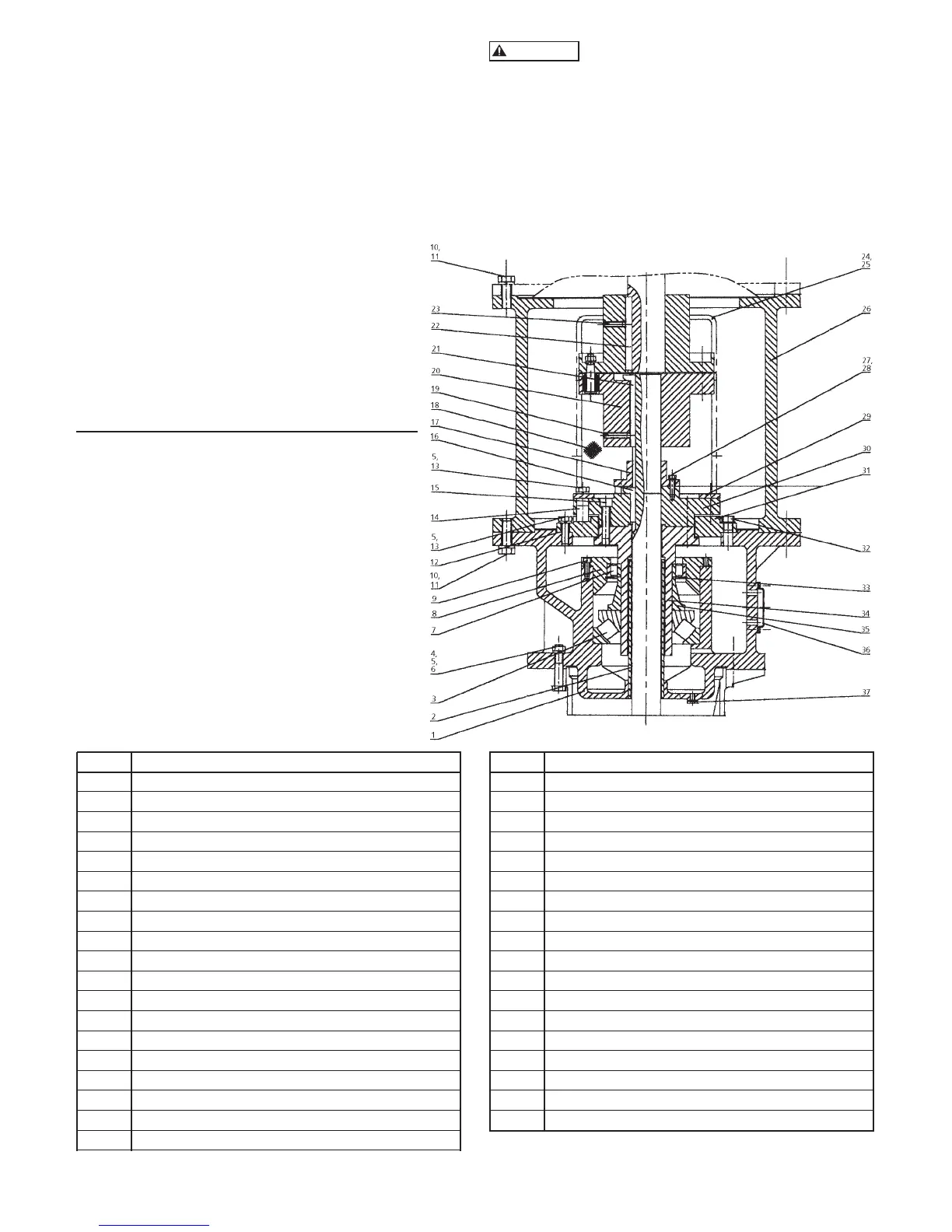
ITEM DESCRIPTION
1 Thrust pot body
2 Tube - oil retaining
3 Thrust bearing
4 Capscrew - head to thrust pot
5 Washer - head to thrust pot
6 Hex Nut - head to thrust pot
7 Roller bearing
8 Bearing seat
9 Allen head screw
10 Capscrew - motor adapter to motor or thrust pot
11 Washer - motor adapter to motor or thrust pot
12 Gasket
13 Capcsrew
14 Non-reverse pin
15 Socket head screw
16 Gib key
17 Adjusting nut
18 Coupling guard
19 Setscrew
ITEM DESCRIPTION
20 Flexible shaft coupling
21 Gib key
22 Key (motor shaft)
23 Setscrew
24 Round head screw for coupling guard
25 Washer coupling guard
26 Motor adapter
27 Capscrew - adjusting nut
28 Washer - adjusting nut
29 Retaining ring
30 Hollow shaft clutch
31 Non-reverse plate
32 Pipe plug - oil filling
33 Retaining ring
34 Hollow shaft
35 Shaft sleeve
36 Sight gauge
37 Pipe plug - oil drain
Figure 19 – Oil Lubricated Thrust Pot