29
pleasing simulation of an acoustic space. We chose the parameters of the cross-feed circuit to nd a
good compromise between accurate imaging and tonal neutrality. For recreational listening there
could be more aggressive modeling of the head related transfer function (HRTF) but this is usually at the
expense of adding tone color. For critical monitoring during the recording/editing/mixing process the
user will nd that the m905 cross-feed circuit provides a sonically neutral character.
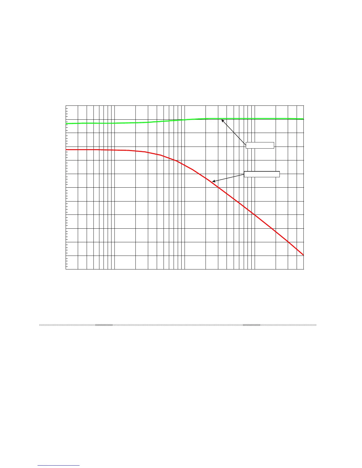
Below is a frequency response plot showing the response of the m905 cross-feed circuit. In this graph
one channel of the headphone amplier is driven. The two traces show the direct channel and the op-
posite (cross-feed) channel.
-55
+5
-50
-45
-40
-35
-30
-25
-20
-15
-10
-5
+0
dB
20 50k50 100 200 500 1k 2k 5k 10k 20k
Direct Signal
Crossfeed signal
<figure - cross-feed response graph>
13 Communication Error Handling
If at any point communication is lost between the RCU and ACU, the remote will display the communi-
cation error message and begin attempting to re-establish communication. During this time, the ACU
remains in the last congured state. Once communication is restored, the remote retrieves the system
status from the ACU and normal operation resumes.