42
19 Wiring Diagrams
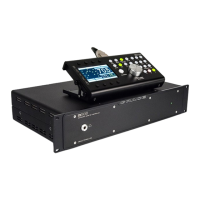
SHIELD
HOT
GND
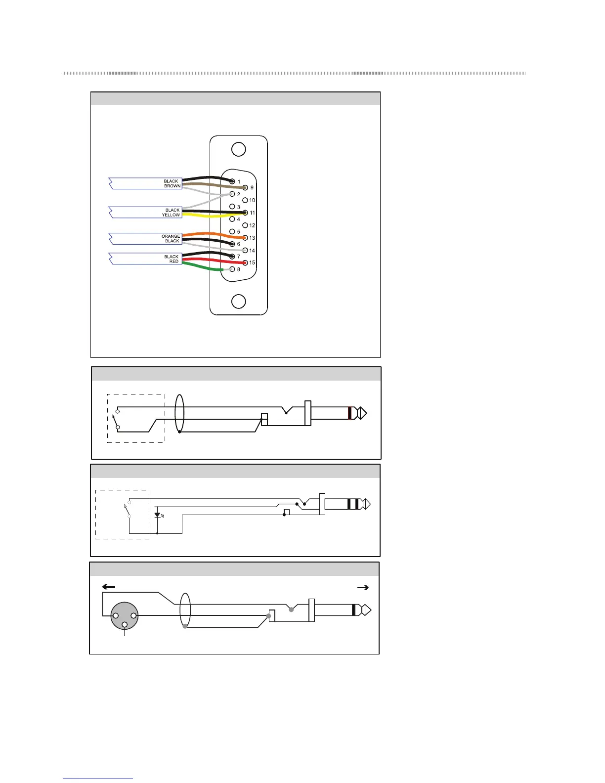
TIP
SLEEVE
Normally open switch
Talkback remote switch diagram
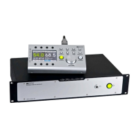
Do not use an o the shelf DB15 cable as the pinout will be incompatable.
If you need a longer cable contact your Grace Design dealer or us directly.
DB15 15 pin RCU connector, RS485 operation
Connector back side veiw.
Both cable ends are identical.
PIN 1 RX-
PIN 2 GND
PIN 3* TX-
PIN 4* +5VDC
PIN 5* GPIO
PIN 6 TALKBACK-
PIN 7 HEADPHONE LEFT
PIN 8 HEADPHONE GND
PIN 9 RX+
PIN 10* TX+
PIN 11 +6.5VDC
PIN 12* +3.3VDC
PIN 13 TALKBACK
PIN 14 GND
PIN 15 HEADPHONE RIGHT
* presently unconnected,
provisional for RS422 operation
1
2
3
SHIELD
HOT
GROUND
(OPEN)
Unbalanced 1/4”
Balanced Output XLR
Balanced XLR output to unbalanced 1/4” input
TALLY
TALKBACK CONTROL
GND
1/4" TRS PLUG
TIP
SLEEVE
LED
Talkback remote switch diagram with LED indicator
To m905 Remote Talkback Jack
Normally open switch
To m905 Remote Talkback Jack