41
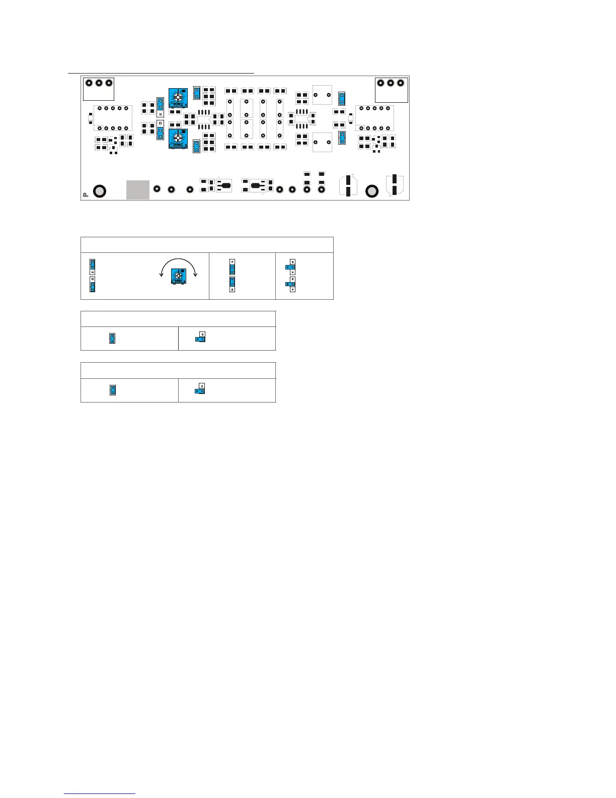
PHONO INPUT MODULE JUMPER LOCATIONS
GAIN
J3, J4
HIGH GAIN
60dB
J3, J4
LOW GAIN
40dB
12Hz SUBSONIC FILTER (HPF)
J5, J6
HPF ON HPF OFF
J5, J6
R14
C6
J3, J4: Closed: Hi Gain
-18V
+18V
R9
R23
C22
U4
J5
C21
L
G R
U2
R16
R13
C10
C13
R18
U3
R20
C12 C15
C7
U1
R11
R10
C8
C9 C11
C16
nEN
R22
C18
GND
R27
R26
R25
C19
C14 C17
R24
R28
R30
J6
R32
R31
C20
R29
D2
C23
MH2
Q4
C24
R33
R34
Q3
K2
Output
R15 R17 R19 R21
AT171
R G
Input
L
J3
J1, J2: Input Z
VR1
D1
K1
MH1
R2
R1
Q2
R3
REV
GND
R4
R6
C2
J2
Q1
R5
R8
C1
R7
J1
-15V
VR2
J4
+15V
C4
C5
R12
C3
P
171 RevA
J5, J6:
Closed:
Subsonic
Filter
CARTRIDGE LOADING
J2
J1
VARIABLE
0-500 Ω
FIXED
100 Ω
J2
J1
FIXED
47K Ω
J2
J1
500Ω
0Ω
VR1, VR2
PHONO INPUT MODULE PCB
CARTRIDGE LOADING J1 and J2 and VR1-VR2 set the cartridge loading.Moving magnet cartridges will
typically be best matched by the 47k Ohm setting.The ideal load for a moving coil cartridge is typically
indicated in the product specications.There are two options for loading moving coil cartridges: 100
Ohms and 0-500 Ohm variable.If you do not know the recommended load for your cartridge, 100 Ohms is
a good place to start. If you know the recommended load then you can use the adjustable setting.
To adjust the cartridge loading to your specied value, connect an Ohm meter to the Left channel RCA
input jack on the rear panel of the m905. Then, using a small screwdriver, turn VR1 until the desired resis-
tance is reached.Repeat for the Right channel by turning VR2.
GAIN J3 and J4 set the preamplier gain.Use the low gain setting for most moving magnet (MM) car-
tridges.These cartridges will typically have an output voltage of 3-10mV RMS. For low output moving coil
(MC) cartridges use the high gain setting.
SUBSONIC FILTER J5 and J6 enable the12Hz subsonic lter.This is a rst order (6dB/octave) high pass lter
for reducing very low frequency information.This is typically turntable rumble and low frequency excur-
sion caused by warped records.Use this to protect the woofers in your speaker system from unnecessary
excursion.